Today built up most circuits in this thread and settled on original Yamaha.
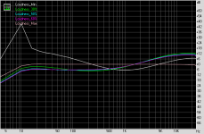
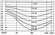
You would not think based on response plots.
But hooked up to a real amplifier sounded great.
I would say, even metaphysical.
Tweaked the input cap and resistor slightly but otherwise its the Yamaha circuit.
Best sound at various spl levels for me was between 5 and 6 on loudness dial.
You would not think based on response plots.
But hooked up to a real amplifier sounded great.
I would say, even metaphysical.
Tweaked the input cap and resistor slightly but otherwise its the Yamaha circuit.
Best sound at various spl levels for me was between 5 and 6 on loudness dial.
Attachments
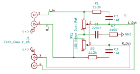
I used 10nF instead of the 8.2nF because can get 1% cheap.
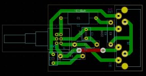
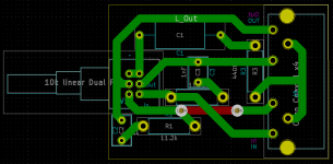
The series resistor waiting for final test 4.7k - 8.2k, doing new pcb.
All other values same.
In the final app it is driven with opa1622 headphone amp.
It requires very lo-z drive. Otherwise weird peaking responses.
The driven output load load on my test ckt is a 20kA volume pot .
It cannot be driven from typical line-out.
Attachments
Last edited:
Thus:
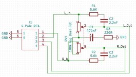
Guys, please help to find where is a mistake in the loudness control.
I used Alps RK09L series potmeter (100k log).
I think first mistake is that the potmeter wired reverse, according to the Freq. resp. measurement.
Questions:
- 10k log better instead of 100k log?
- Or I have to adjust the resistor size to 100k log?
Or there are another mistake?
Thanks
Laszlo
Attachments
Last edited:
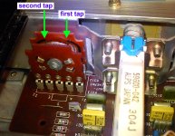
R1 and C2 must be connected to loudness tap, not to wiper.
Edit: this is not usual loudness circuit, bass eq is mono?
Strange, with potentiometer without loudness tap I would copy some old circuit from old amps/receivers that use this standard potentiometer.
But I never saw connection like this. Volume pots are always connected to ground, your is summed to mono and that connected to cap and resistor to ground.
Last edited:
What specifically is the problem with it?
If presonus has a headphone out use that for drive as a test.
I measured this freq. resp.
Attachments
R1 and C2 must be connected to loudness tap, not to wiper.
Edit: this is not usual loudness circuit, bass eq is mono?
Strange, with potentiometer without loudness tap I would copy some old circuit from old amps/receivers that use this standard potentiometer.
But I never saw connection like this. Volume pots are always connected to ground, your is summed to mono and that connected to cap and resistor to ground.
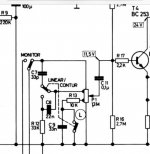
I followed a wrong schematic. I designed based on Loudness stage
instead of
Loudness stage
the R1 location is wrong.
I made a mistake too, sorry.
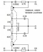
I was thinking that this is classic loudness on volume potentiometer, but this is Yamaha type of variable loudness, after the volume pot.
I changed the pot. from100k to 10k and according the original description I doubled the resistor values, and halve the capacitance, and it's working now. Thanks

- Home
- Source & Line
- Analog Line Level
- Loudness stage