Member
Joined 2009
Paid Member
Member
Joined 2009
Paid Member
Bigun said:phew, that's good.
Now for a crazy idea.
Not so crazy - I considered a kind of bridged super symmetrical idea for higher power, mirroring the circuit to operate on a V- side of a split supply. Still pondering...
For now, for the application I have in mind, I'll leave it as is. I just need to get the time (and motivation) to puzzle out a board.
Member
Joined 2009
Paid Member

Member
Joined 2009
Paid Member
Bigun said:You gotta do it, you just hafta do it !!!
Yes! YES! Ahahahahahaaaa! (ripped from DX - deep yet somewhat condescending laughter
") )
)Heheheheheeee!
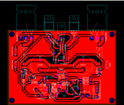
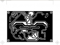
First step - copper bottom pdf:
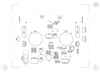
Attachments
Member
Joined 2009
Paid Member
Originally posted by MJL21193 Yes! YES! Ahahahahahaaaa! (ripped from DX - deep yet somewhat condescending laughter
Indeed, I am sometimes looking over my shoulder expecting to see him!

Member
Joined 2009
Paid Member
How's it going with the construction MJL21193 ?
I am thinking that if I build this amp I should change the input device to a CFP - it's become my favourite compound device these days - would it work, would it help, did you try this in your sims ?
Perhaps a JFET/BJT CFP - what are your thoughts on this ?
I am thinking that if I build this amp I should change the input device to a CFP - it's become my favourite compound device these days - would it work, would it help, did you try this in your sims ?
Perhaps a JFET/BJT CFP - what are your thoughts on this ?
Member
Joined 2009
Paid Member
Nelson Pass said:You can improve it a bit by putting some resistance in series with
the emitter of the BJT, say 47 ohms.
If you want lower distortion, use another 2SK170 as a current
source to the -9V rail instead of the 820 ohm, and then maybe
load the output with 10K or 20K to ground.
Tried all that and it's wasted effort - B1 still sounds better.
The shematic presented above is just for illustration - JFET/BJT CFP looks attractive but results are sonicaly disappointing.
Member
Joined 2009
Paid Member

I disagree, I find JFET/BJT CFP input stage the most alive and least dull of the input stages I've tried.juma said:I don't want to rain on your parade but JFET/BJT CFP is a rather disappointingly sounding gain block (dull, lifeless). IMO it can only be used as a unity gain buffer in guitar preamp - something like this:
Bigun said:How's it going with the construction MJL21193 ?
I am thinking that if I build this amp I should change the input device to a CFP - it's become my favourite compound device these days - would it work, would it help, did you try this in your sims ?
Perhaps a JFET/BJT CFP - what are your thoughts on this ?
I'm still stalled. I haven't done anything since.
The CFP (bjt type) works fine in simulation, though there doesn't seem to be any measured improvement - THD the same.
What does make an improvement to this circuit (at least in simulation) is another "gain" block at the input - a high beta, NPN emitter follower at the input. I was playing with this before and may (will) include it in future testing.
As for FETs, I'm still watching and learning. I have some included on my next Digikey order - Zetex ZVN/ZVP to tinker with.
- Status
- This old topic is closed. If you want to reopen this topic, contact a moderator using the "Report Post" button.
- Home
- Amplifiers
- Solid State
- Looking for Feedback on this No Feedback Amp.