Wavebourn said:The next time you may want to try a source follower loaded on a counter-modulated CCS. However, it will require some servo.
As my knowledge grows, I'll explore other variations. For now, I think I'll leave this as is and build it up. Should be a good sounding amp.
jam said:That is a similar output stage used by Matti Otala in his groundbreaking design from years ago.
I hadn't seen anything by Otala until today, here - posted by Jan Didden. Yes, the driver arrangement is the same.
Jam, can you make any suggestions for improvement?
Bigun said:Back to 'single' supply - I like that better.
What is R16 - is it some kind of zobel ?
The dual supply thing in the post above was something I was trying out in simulation and accidentally left it in as I posted the pic. Ignore it please
R16 will bleed the output cap when a speaker is not connected. Without this, the cap will charge and when you connect the speaker...!
You are right, MJL21193. The driver arrangement is the same, but "the everything" arrangement is different: currents, voltages, other "devil" details. Hence, speeds, transients, behavior when overdriven.
By the way, Johannes: I've got a mail! Thank you for the HB 4 months before!
By the way, Johannes: I've got a mail! Thank you for the HB 4 months before!

Wavebourn said:You are right, MJL21193. The driver arrangement is the same, but "the everything" arrangement is different: currents, voltages, other "devil" details. Hence, speeds, transients, behavior when overdriven.
Well, they are totally different amps, just that driver arrangement in common.
The "devil" (is in the) details show a well behaved, low distortion amp. No miracle ultra low THD, high slew rate million parts count beast but a simple little thing. What I was aiming for really.
Clipping behavior is very clean - no sticking or instability. When I get a chance, I'll post some scope shots of the amps clipping performance.
Thanks jam,
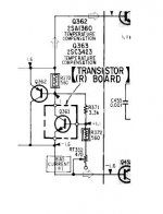
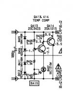
What are your suggestions for the bias network?
More playing around:
I will reduce R7 to 1.3K and R8 to 1K. This will increase current through the drivers and balance them a bit better.
With the increased current, I will probably use 2SC4793/2SA1837 for these rather than the 2SC3503/2SA1381.
What are your suggestions for the bias network?
More playing around:
I will reduce R7 to 1.3K and R8 to 1K. This will increase current through the drivers and balance them a bit better.
With the increased current, I will probably use 2SC4793/2SA1837 for these rather than the 2SC3503/2SA1381.
Member
Joined 2009
Paid Member
Apply square signal at the input and watch close fully the voltage across new bias circuit for any signs of instability. D.Self warned us about possible stability problems that may arise when using this kind of bias circuit.
I have used this circuit (in simulation only) and I have seen some ringing with square signals. Putting an compensation capacitor between BC of second bias transistor helped a lot.
I have used this circuit (in simulation only) and I have seen some ringing with square signals. Putting an compensation capacitor between BC of second bias transistor helped a lot.
Hi Gareth,
The way I understand it this new Vbe multiplier will hold the bias current steady, more accurately than the single T one - probably a good thing in a class A amp.
Having ran a few simulations, I will (potentially) change cdom to 22pF, depending on the real amp performance. The sim shows unstable operation at 15pF (confirmed in the real amp during tests and I didn't have a 22pF to try at that time) but proper compensation at 22pF. Worth a try.
Hi bluesky,
I will follow your advice. I tried this Vbe before on my patchwork amp with mixed results - stability was fine but I had other problems. The simulation looks good for stability in this configuration. I will be getting a preliminary board layout together (soon, I hope - too much work lately) to try and test.
I will follow your advice. I tried this Vbe before on my patchwork amp with mixed results - stability was fine but I had other problems. The simulation looks good for stability in this configuration. I will be getting a preliminary board layout together (soon, I hope - too much work lately) to try and test.
Member
Joined 2009
Paid Member
I agree with Blueskynis, CFPs like to dance and I'm still not through finding all the oscillation possibilities in my own sims.
I did find it helpful to include some degeneration on the emitter of the slave device. I think on your schema that means 22R on the emitter of U5 (actually U4 but this is where you want it I think).
How do you adjust the 'dc' offset at the output ? - I know there's a cap, I'm thinking about the fact that you want the 'dc' on the amplifier side of the cap to be half way between the supply rails to maximize the up and down swing you can get. How do you set this - or is it simply close enough from the symmetry of the topology ?
Bigun said:I did find it helpful to include some degeneration on the emitter of the slave device. I think on your schema that means 22R on the emitter of U5 (actually U4 but this is where you want it I think).
A quick breakdown of this topology (if I understand it correctly myself
Q2 and Q3 are the closet to a CFP - they are the "differential transconductance amp" Rick referred to with the base of Q2 as the non inverting input and the emitter of Q2 as the inverting input. R13 is the feedback resistor.
Q3 is effectively the VAS with U5 as a voltage buffer with current gain.
Q4 and U4 are the Vbe multiplier.
Bigun said:
How do you adjust the 'dc' offset at the output ? - I know there's a cap, I'm thinking about the fact that you want the 'dc' on the amplifier side of the cap to be half way between the supply rails to maximize the up and down swing you can get. How do you set this - or is it simply close enough from the symmetry of the topology ?
The DC at output is nearly 0 - the cap blocks DC.
The single supply means, as you say, there has to be a mid point for the signal to swing. As there is no negative rail, the reference is somewhere close to half the supply voltage. The 10K pot - R1 adjusts this point.
Member
Joined 2009
Paid Member
I might be mixing this up, but I thought you have introduced a CFP as your Vbe multiplier ? And in this design the master is U4 and the slave Q4. The master provides a signal to the slave via the collector - base connection. Current flow in the master is held low by R12, the slave does the heavy lifting of course. In my LTP it is the emitter of the master that required degeneration, which if this is at all relevant in your design would mean including a resistor between the emitter of U4 and the emitter of U5. Even I have confused myself now 
- Status
- This old topic is closed. If you want to reopen this topic, contact a moderator using the "Report Post" button.
- Home
- Amplifiers
- Solid State
- Looking for Feedback on this No Feedback Amp.


