Never really explored that device. I just wanted to make the point that the quasi-sat is a necessary evil for many high voltage processes and every circuit position needs to be optimized. One handle is current density so a medium power 120V + device might be the best Vas choice. Did you look at any of those like the 2N3440 (old school)? A TO92 at 10mA and ~60 - 100V is marginal on PD in the first place.
Good point on power dissipation for TO-92 at 10mA. But in an IPS at only 1-2mA/device, it is not much of a problem. Nevertheless, I have been tempted a couple of times to use a good pair of TO-126 devices in the IPS LTP.
Cheers,
Bob
I believe JLH mentioned using a small signal mosfet for "infinite beta" cascoded by a BJT for VAS
and there are other "cascode" options:
and there are other "cascode" options:
transistors are cheap today - why obsess over "the best one" when two cheap Q can give order of magnitude better performance than "the best one"
cascode with base current reinjection http://web.archive.org/web/20130529..._lab/malcolmspubdocs/J10 Enhanced cascode.pdf
or the "Baxandall Super Pair" - which we should properly credit to Boxall (try forum Google Search)
these do increase the order of the response - introduce the possibility of RF oscillation - which can be tamed with little compromise to their audio frequency performance
But 2sc3503f looks worrying with quasi-sat below Vce 10V, especially when used for the VAS
It's intriguing when overlaid with the Sanyo curves, since they have Ic-Vce curves in relative detail at the same range.
The 2SC3601 curves basically agree that below the point marked quasi saturation exists, but the characteristic curvature in the datasheet doesn't match - the traced curves look a lot more like what is happening on the PNP device.
However the 2SC3503 curves are not in agreement at all with respect to the occurrence of quasi saturation.
I believe JLH mentioned using a small signal mosfet for "infinite beta" cascoded by a BJT for VAS
For the VAS, Linsley-Hood used :
a Mosfet VN1210 in his Mosfet power amps
- in Electronics World and Wireless World, March 1989 (using VP0808s for the input pair and the controlled device of the CCS of the VAS) and also in EWWW, June 1993
- in Electronics Today International, May 1989.
a bipolar cascode BC184 - BF870 in his IGT power amp
- in EWWW, May 1992.
I did'nt see he ever proposed a VAS using a cascode combining a Mosfet + a bipolar.
Groner proposed a very attracting scheme using a 2N7000 Mosfet in source follower mode between the input stage (cascoded and Wilson 3 current mirror loaded) and the main VAS bipolar transistor.
Figures #48 and 50 of http://www.nanovolt.ch/resources/power_amplifiers/pdf/audio_power_amp_design_comments.pdf
Last edited:
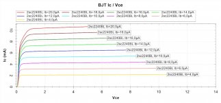
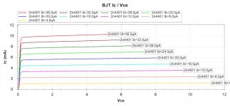
I measured some medium-power (TO-126) and high-power transistors (TO-220) to see whether they exhibited any quasi saturation. Only two of them did.
_
Hi Mark,
The plot of the 2SC3503 you show does not look very good. However, I'm looking at the datasheet and it does not look that bad at all. At 10mA, the knee of the curve appears to be below 1.8V. At 20mA, the knee of the curve appears to be at about 2V.
The datasheet shows beta to still be above 150 at 10mA and 2V, and still above about 140 at 1V.
I assume you are plotting these curves with base current as the parameter, as usual. Its unfortunate that the curve tracer appears not to label the curve parameter with the current value.
Anyway, what do you think the disconnect is here? Do you think that the datasheet is that profoundly wrong? Or am I totally mis-interpreting something?
Cheers,
Bob
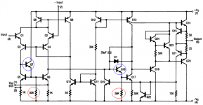
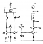
Easiest way to get the benefits of MOSFET infinite input impedance, is to redeploy the original 741 opamp's current mirror load, but replace bipolar emitter followers Q7 and Q16, with MOSFET source followers M1 and M2. Be sure to match the MOSFET load resistors R1 and R2, just as Fullagar matched the 50K emitter load resistors in the 741. We're not building a low power opamp so we can use source leg resistors a lot lower than 50K! Fortunately we can buy dual MOSFETs whose two devices are manufactured side-by-side on the same wafer, see pdf datasheet attached. Although the circuit doesn't require excellent matching, we get it "for free" by purchasing a monolithic dual. USD 0.111 in qty=100.
Now the first stage has enormous voltage gain (= gm * ro_Q4) because it's driving a very high impedance load: M1. And the second stage amplifier Q5+Q6 is driven by a reasonably low impedance source: M1. Very nice!
_
Now the first stage has enormous voltage gain (= gm * ro_Q4) because it's driving a very high impedance load: M1. And the second stage amplifier Q5+Q6 is driven by a reasonably low impedance source: M1. Very nice!
_
Attachments
Last edited:
The plot of the 2SC3503 you show does not look very good. However, I'm looking at the datasheet and it does not look that bad at all.
Anyway, what do you think the disconnect is here? Do you think that the datasheet is that profoundly wrong? Or am I totally mis-interpreting something
Bob, why don't you plop a few of your 2SC3503s on a curve tracer and post the results here? Maybe there's huge unit to unit variation among transistors of this part number. Or maybe my curve tracer is really terrible.
Another thing you could try is to view all available datasheets from all 2SC3503 manufacturers. Maybe the first datasheet you looked at, is terrible (??!?). Octopart says that Fairchild, Moto/ONsemi, and Sanyo all make 2SC3503. Additionally, there is another part called KSC3503 which is made by Fairchild and by "KEC" (Korea Electronics Corporation), perhaps their datasheets will give some insight.
Hi Mark,
I used the KSC3503 datasheet from Fairchild.
It is certainly perplexing, since most of your other transistor curves looked quite good. That would suggest that your curve tracer is OK.
Is there a way on that curve tracer to display the base current corresponding to each curve?
Cheers,
Bob
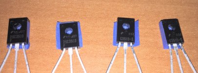
It does begin to appear that the 3503's really do exhibit quasi saturation. I dug out two units of 2SC3503F (highest beta grade) and two more units of KSC3503E (2nd highest beta grade). They are shown in the attached picture. Unit#1 is on the left, Unit#4 is on the right, and they are shown in ascending numerical order. In the photo the stylized capital_F is the Fairchild logo. Blue tape on the back gives me a place to mark the unit#.
All four transistors showed quasi saturation on two different curve tracers. The first is the LockyZ "intelligent" curve tracer sold right here on diyAudio. The second is a low-price, medium-quality, commercial device "CTR101" I bought online. Google can tell you more about it if you're interested.
LockyZ curves include the word "LockyZ" at lower right.
CTR101 curves are solid red lines. Their filenames end in the letter S: Unit_1S.PNG et cetera.
To recap: two units of part type 2SC3503F , and also two units of part type KSC3503E, all show quasi saturation. They show it on two different curve tracers. Pretty convincing if you ask me.
_
Attachments
Thanks Mark for your input: I once got into trouble with different bipolar transistors with my early Levinson JC-1 type design back in 1979. I tried to use some extra super, ultra low noise Japanese transistors and they failed to work properly at low voltage. Scott then attributed it to Quasi-saturation. He was probably right. For reference, the 2N4401 was the primary transistor that was first successful in this low V design (+/- 1.5V). Other large area transistors worked as well, but the LOWEST rbb' devices that I could find, didn't. The only clue to the difference in the devices was peak current (50ma vs 600ma) so what Scott just said might be the primary reason.
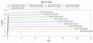
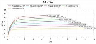
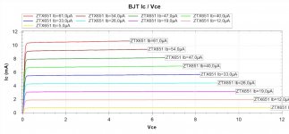
Thanks John! Based on the curve tracer data presented here, I would expect the BC337-40 and the ZTX851 to have the greatest success at 1.5 volts: their IV curves act like transistors at the lowest Vce of all. Datasheet IceMax values are 0.8A and 5.0A respectively. Recall that ZTX851 is the world's champion lowest rbb' NPN at 1.67 ohms according to AOE 3rd edition.Other large area transistors worked as well, but the LOWEST rbb' devices that I could find, didn't. The only clue to the difference in the devices was peak current (50ma vs 600ma) so what Scott just said might be the primary reason.
Regrettably hobbyists don't have access to any simulators that offer the Mextram (or VBIC) models. You gotta pay 1.0-2.0 Mercedes Benz sedans to get one. price link
I make quite a nice living designing ICs using SPICE; it has paid for both of my houses here in Silicon Valley. Several startup companies I've worked for, bet the company on SPICE and won the bet. It's quite a useful tool, in the hands of a well-trained & seasoned professional.
Ingenious fools can obviously do a lot of damage if they get their hands on pro-grade tools, like a scalpel or a bulldozer or SPICE. Wielded by a professional, these tools can perform miracles. Wielded by a dunce, they can wreak havoc.
Ingenious fools can obviously do a lot of damage if they get their hands on pro-grade tools, like a scalpel or a bulldozer or SPICE. Wielded by a professional, these tools can perform miracles. Wielded by a dunce, they can wreak havoc.
I make quite a nice living designing ICs using SPICE; it has paid for both of my houses here in Silicon Valley. Several startup companies I've worked for, bet the company on SPICE and won the bet. It's quite a useful tool, in the hands of a well-trained & seasoned professional.
Ingenious fools can obviously do a lot of damage if they get their hands on pro-grade tools, like a scalpel or a bulldozer or SPICE. Wielded by a professional, these tools can perform miracles. Wielded by a dunce, they can wreak havoc.
Well stated, Mark.
No simulator is perfect and no models are perfect, but the value-added is remarkable in a design as long as the simulation results are tempered with experience and good interpretation. Simulation, as helpful as it is, is certainly not a replacement for thorough testing and measurement of a prototype, and in audio, listening tests.
Given the low cost and wide availability of SPICE (LTspice is free), I believe it is foolish to not simulate an amplifier design before building it.
Cheers,
Bob
more traces
Attachments
-
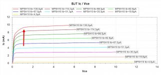 MPSH10.jpg80.4 KB · Views: 443
 -
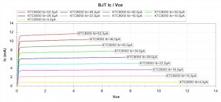 KTC8050.jpg81.8 KB · Views: 406
 -
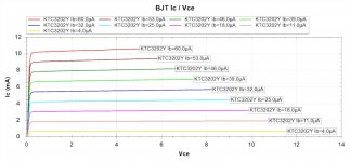 KTC3202Y.jpg82.1 KB · Views: 394
 -
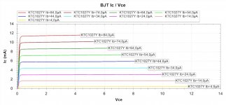 KTC1027Y.jpg80.8 KB · Views: 410
 -
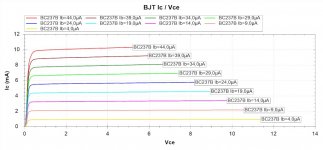 BC237B.jpg78.4 KB · Views: 457
 -
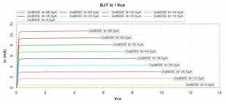 2SD600E.jpg78.4 KB · Views: 452
 -
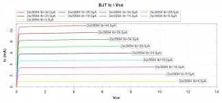 2SC5694.jpg81.1 KB · Views: 431
 -
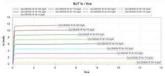 2sc3940AR.jpg83.4 KB · Views: 455
 -
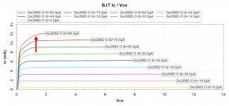 2sc2682O.jpg82.7 KB · Views: 836
 -
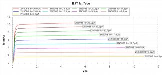 2N5088.jpg77 KB · Views: 863
- Home
- Amplifiers
- Solid State
- Looking for a small signal NPN with no Quasi Saturation: MEASURED DATA