Pretty sure? There's got to be something wrong though. The distortion isn't normal even for a tube amp. It sounds fine up until a peak signal clips it and I hear a snapping/popping from the speaker. All my output tubes are new EH 6V6s and my 12AX7s are used but I've tried swapping them around with the same result.
This was my first cathodyne circuit but it's based of other's I've found online operating at the same voltages (280vdc).
Late last night I built the right channel into a paraphase inverter to see how that sounds but I haven't been able to try it yet. I came home late tonight as well so no testing for me until morning.
How does one figure the voltage across a cathodyne? Is there a starting point for max swing? Say, anode at 75% B+, cathode at 25% B+? In that example, 280v B+ would translate into 210v at the anode and 70v at the cathode which makes 140v across the tube.
Could be the onset of oscillation... just saying. You could try to add a series group of say 470pF and 4,7K across the first plate resistor in the amp to limit HF response ( you won't hear the difference probably).
Or you may have some bad / worn tube there that just makes noise or socket imperfections... I have annoying crackle sometimes, usually until the heater is... heated to it's full temperature and stops clicking (you might even hear that if near the tube).
Or you may have some bad / worn tube there that just makes noise or socket imperfections... I have annoying crackle sometimes, usually until the heater is... heated to it's full temperature and stops clicking (you might even hear that if near the tube).
The first plate in the first gain stage?
I don't know how much this had to do with the snapping issue but... On one channel, I had the screen of one tube wired to B+ (triode) and the screen of the other tube wired to slightly lower B+ (pentode?). That could have caused an issue. I don't know how I managed that. I have yet to test it again.
What does a saturated transformer sound like? My OPTs are pretty small.
On another note, I made my first single mosfet class-a amp tonight. Works great.")
I don't know how much this had to do with the snapping issue but... On one channel, I had the screen of one tube wired to B+ (triode) and the screen of the other tube wired to slightly lower B+ (pentode?). That could have caused an issue. I don't know how I managed that. I have yet to test it again.
What does a saturated transformer sound like? My OPTs are pretty small.
On another note, I made my first single mosfet class-a amp tonight. Works great.
The age old question; do you have an osciloscope .
It would help a lot to see the waveform during this crackling sound.
To determine the voltages at the anode and cathode of a cathodyne, you first find the voltage across the triode. This is done by drawing a loadline using the value of both resistors as the load. Next choose the biaspoint to find the voltage at the anode. Subtract the voltage from B+ and you'll know how much is 'left over' for the resistors. Divide this by two to find the cathode voltage and subtract this from the B+ to find the actual anode voltage.
Since you know the bias point and therefor the operating current, you can also multiply this current by the resistor value (U=I*R) to find the voltage across each resisitor.
.It would help a lot to see the waveform during this crackling sound.
To determine the voltages at the anode and cathode of a cathodyne, you first find the voltage across the triode. This is done by drawing a loadline using the value of both resistors as the load. Next choose the biaspoint to find the voltage at the anode. Subtract the voltage from B+ and you'll know how much is 'left over' for the resistors. Divide this by two to find the cathode voltage and subtract this from the B+ to find the actual anode voltage.
Since you know the bias point and therefor the operating current, you can also multiply this current by the resistor value (U=I*R) to find the voltage across each resisitor.
Have you considered the Heater to Cathode potential somewhere in the amp????
Possible break-down at peaks.... The crackling sound is typical of this type of issue...
Your Heater to Cathode potential is the (DC voltage at the Cathode + Peak AC signal) with respect to Heater voltage...
Possible break-down at peaks.... The crackling sound is typical of this type of issue...
Your Heater to Cathode potential is the (DC voltage at the Cathode + Peak AC signal) with respect to Heater voltage...
6V6 has a 200v heater to cathode rating so I should be ok. My cathodes are at about 19v and each heater lead is grounded via. two 300ohm resistors.
I had a chance to drive it tonight and all is well. It must have been my error in wiring. Guess I'll be checking three times next build.
I'm still learning the load lines. My understanding now is that if I pick a lower current and/or higher voltage I'll get more output voltage swing but too little current and I wind up in that non-linear area. Is this correct?
I'm still learning the load lines. My understanding now is that if I pick a lower current and/or higher voltage I'll get more output voltage swing but too little current and I wind up in that non-linear area. Is this correct?
If using a very large anode load resistance, the loadline will be driven to close to the abscissa, the part close to the X-axis where the grid curves become bundled together again. Gain will actually fall and performance becomes unpredictable. I haven't seen a 12AX7 design (yet) with more than 470k anode load.
Too little current is not really a concern AFAIK, since the grid of the next stage has very high impedance (not talking about the gridleak resistor). What is a concern however, is the fact the output impedance of the stage will increase with a larger anode load resistor. Powertubes for example usually have smaller values gridleak resistor, which mostly determine the load presented to the preceding stage. They might prove to heavy to drive and induce a lot of attenuation when the output impedance increases, negating the increased voltage gain.
6V6 has a 200v heater to cathode rating so I should be ok. My cathodes are at about 19v and each heater lead is grounded via. two 300ohm resistors.
I had a chance to drive it tonight and all is well. It must have been my error in wiring. Guess I'll be checking three times next build.
I'm still learning the load lines. My understanding now is that if I pick a lower current and/or higher voltage I'll get more output voltage swing but too little current and I wind up in that non-linear area. Is this correct?
Yes..you are correct.... Back in the early 60's using very large plate resistor with very low current was referred as "starvation mode" .... In order to get a large Gain.... as in non-linear gain... This was great to use in some non-audio circuits where harmonics were of little concern...
If you are looking for more linear Gain..then try another type of circuit..
You mention CATHODYNE in earlier post... double check your heater to cathode voltage.... not just the DC voltage but look at the peak AC signal summed on top of your DC voltage..The Cathodyne can take in a big signal voltage..
Last edited:
Thanks for all the input so far. It's helping put the pieces together.
On the topic of impedance... If I run a pair of 6BQ5s at 350v, I think an 8k OPT would work. I need 2/4/8 ohm output impedance. If I run a 16k OPT with 4/8/16 ohm impedance, would connecting a 4 ohm speaker to the 8ohm tap yield 8k primary impedance? Is something like that common practice?
When connected normally, Is an 8k PP OPT 8k-0-8k or 4k-0-4k?
Thanks for all the input so far. It's helping put the pieces together.
On the topic of impedance... If I run a pair of 6BQ5s at 350v, I think an 8k OPT would work. I need 2/4/8 ohm output impedance. If I run a 16k OPT with 4/8/16 ohm impedance, would connecting a 4 ohm speaker to the 8ohm tap yield 8k primary impedance? Is something like that common practice?
When connected normally, Is an 8k PP OPT 8k-0-8k or 4k-0-4k?
When you figure the LOAD-LINE ..use the full power output voltage...Not the idle voltage.... ie The power supply will dip at full output power... and that is when you are at full excursion of the AC swing on the load-line...
AT 350V for that tube...you will be at at Class AB1... The screens draw current and also will dip a bit more than the supply... 8K is roughly a good number for a pair of 6BQ5 in that voltage range... I prefer to stay to the right side of the knee, thus maintaining the plate resistance at full AC excursion..so I typically use 7.6K .... With bigger plate loads you go to the left side of the 0-bias curve knee at full power, your plate resistance drops low to TRIODE range and goofs up the frequency response and distortion..
When you look into each side of a Push-Pull transformer with respect to the Center-Tap you will get 1/4 the plate load...ie, the Load-Line..
With different Class of operation things get a bit more complex...
When you look into each side of a Push-Pull transformer with respect to the Center-Tap you will get 1/4 the plate load...ie, the Load-Line..
With different Class of operation things get a bit more complex...
You lost me.
I intend on a regulated B+ by the way.
No schematic yet as I'm deciding on what type of phase inverter to use and also studying triodes used in the gain stage which are class-a and easy to figure for the most part.
The thread is a little all over the place because of my other questions but it started with how to plot a load line, where to choose "the dot", and how plate resistors effect gain. I was attempting to apply this knowledge to a paraphrase in attempts to get equal signal level from both phases.
I used a paraphase schematic I found online but the outputs are not equal. My second stage is significantly louder then the first. I'm thinking that adjusting the gain using the plate resistor wouldn't be a good idea because it's linearity will become significantly different then the first stage. I think I'll stick with the simple resistor divider off the output's grid (how it's currently wired) and adjust resistor values for equal signal levels. I'm going to have to do this with a pot though and then measure it because the math just isn't working out for me.
My other option is a cathodyne with gain stage afterwards like the Williamson but two coupling capacitors are eliminated with a paraphase.
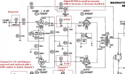
magnavox paraphase
You might look here for some help Paraphase Inverter Gain and Resistor Values
I built the magnavox circuit and used a pot for R10 (22k) the balancing resistor. I put a scope on both grids of the 6V6's and adjusted the pot until I got a balanced output. Then measured the value and replaced with a resistor.
Steve
Attachments
You might look here for some help Paraphase Inverter Gain and Resistor Values
I built the magnavox circuit and used a pot for R10 (22k) the balancing resistor. I put a scope on both grids of the 6V6's and adjusted the pot until I got a balanced output. Then measured the value and replaced with a resistor.
Steve
That's just what I had in mind.
Why not use a long tailed pair phase inverter? More linear than the paraphase and although it's a two-tube solution, it comes with some gain of its own, in contrary to the one-tube cathodyne.
I don't think tube linearity is as critical in a push pull amp, is it?
The LTP is a pair of triodes just like the Paraphase. Or were you adding a second triode as a gain stage?
Well, everything from input to output adds up. Any nonlinearity introduced is amplified by the next stage, wether it's SE or PP.I don't think tube linearity is as critical in a push pull amp, is it?
The LTP is a pair of triodes just like the Paraphase. Or were you adding a second triode as a gain stage?
The thing I dislike about the paraphase, is its non symmetrical topology. The signal amplified for one half of the output stage, is first attenuated and then put through another common cathode stage for the other half, introducing possible noise and distortion in the process. I find the LTP to be more graceful is this respect. But to each his own off course.
Another benefit is the ease of how apply feedback if desired.
Having read these two articles, the LTP seems like a bit of a pain.
http://www.freewebs.com/valvewizard/acltp.html
The Valve Wizard
http://www.freewebs.com/valvewizard/acltp.html
The Valve Wizard
I'm playing with the paraphase and listening to the output of the first stage using my headphones with a 10k resistor and .1 capacitor in series to the plate.
I have a 12ax7 using two 100k plate resistors to 250v b+ and a 1.8k cathode resistors to ground with a parallel 47uf cap. I measure about 1.6v across it. When I place a pot in parallel with the cathode resistor and bring that voltage down to .5v it sounds MUCH better. The distortion is significantly reduced. My input would swing the grid positive in this case. Is there any problem with the grid going positive?
I must be doing something wrong because when I build things off schematics I found online it sounds like crap but if I just start messing around (like the example above) I can get it to sound much better.
Edit - Actually the B+ was closer to 300v. Output tubes are removed. It makes sense that what I'm doing sounds better because this is putting the plate at 1/2 B+ or 150v. Class A. This doesn't coincide with the load line calculation though.
Last edited:
- Status
- This old topic is closed. If you want to reopen this topic, contact a moderator using the "Report Post" button.
- Home
- Amplifiers
- Tubes / Valves
- Load lines. What?