What kind of headphone and what is its impedance?I'm playing with the paraphase and listening to the output of the first stage using my headphones with a 10k resistor and .1 capacitor in series to the plate.
Perhaps it sounds better because of the particular load that you have (see above), and/or you prefer certain forms of distortion. It is never a good idea to have positive grid, especially for tubes that are not specifically designed for it such as the 12AX7.When I place a pot in parallel with the cathode resistor and bring that voltage down to .5v it sounds MUCH better. The distortion is significantly reduced. My input would swing the grid positive in this case. Is there any problem with the grid going positive?
Something is indeed wrong...I must be doing something wrong because when I build things off schematics I found online it sounds like crap but if I just start messing around (like the example above) I can get it to sound much better.
")
I've got a hard time picturing the actual circuit you're working with. Are the two 100k resistors in parallel or series, is the 47uF cap still in place with the extra cathode pot, what's the actual load presented to the output and how is it connected, all important variables to determine what's going on.
Driving the grid positive is not a problem per se. Grid current will flow and it will chop off the amplified bottoms.
Driving the grid positive is not a problem per se. Grid current will flow and it will chop off the amplified bottoms.
They are 32ohm headphones with a 10k resistor and .1uf cap in series.
I probed headphones on to pin 6 and pin 1. The first paraphase I built using a schematic I found online and pin 1 was significantly louder. I then emulated the circuit shown and a 9.2k on the voltage divider gives me near perfect balance both in the emulator and in the headphones.
I turned up the signal level into pin 7 while listening to pin 6 and I can drive a much higher signal (before distortion) if I bring the cathode pin 8 down from 1.6~1.8v to 0.5v.
It also shows the same results in the emulator. The waveform begins to clip at 1.5v input with the 1.8k shown. If I replace the 1.8k with 680Ω the clipping goes away.
Attachments
Last edited:
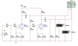
Thanks for the schematic; now we can all understand your circuit.
V1A is a voltage amp; it drives input A of XSC1 and the grid of V1B through a voltage divider composed of R7 and R4. Most of the signal to the grid of V1B is shunted to ground by the voltage divider; you found the correct resistance ratio for the voltage divider empirically. In theory it should be the same voltage amplitude as the input to V1A, assuming both halves of the tubes have the same mu.
This was an excellent exercise in understanding triode circuits, but it is not an efficient or elegant circuit for phase splitting. Study the Mullard 5-20 circuit for a basic implementation of the LTP phase splitter. Many current builders find that an updated Mullard 5-20 circuit using a triode voltage amp instead of the pentode and a CCS under the tail of the LTP gives very satisfying sound.
http://www.diyaudio.com/forums/tubes-valves/242483-mullard-5-20-build-mods.html
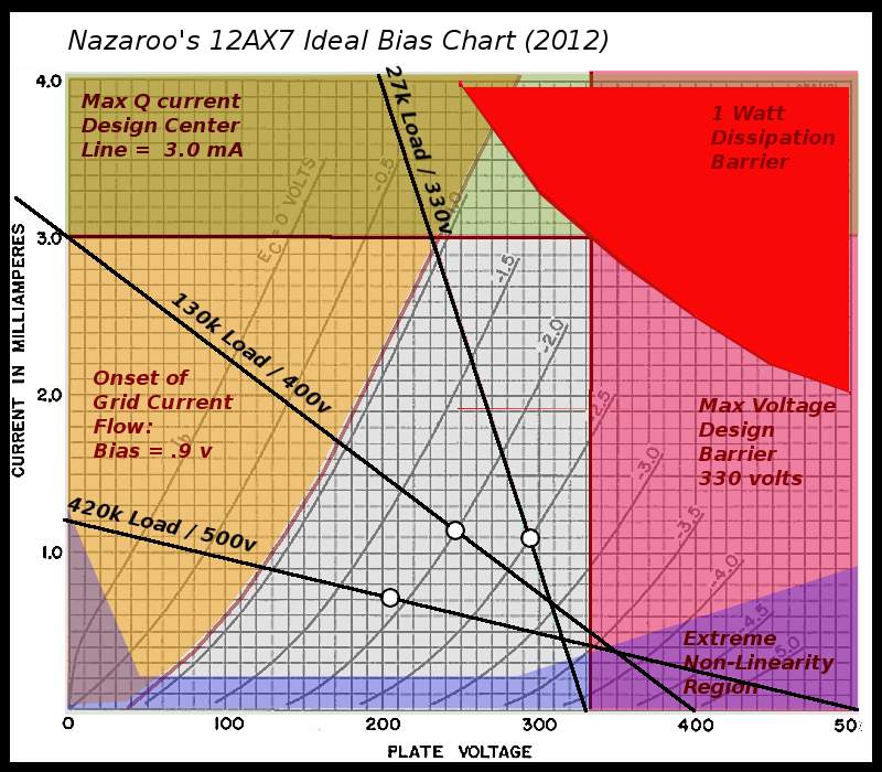
Well, a 10032 ohm load, possibly in parallel with 470k ohm (making 9822 ohm), is a waaaay to heavy a load for a common cathode 12AX7. For analysis, you can draw an AC loadline (see pic below, the green line). As far as AC is concerned, the anode resistor and following load are in parallel as well. The green line shows the actual response. As you can see, it's almost vertical and performance will degrade.
A 12ax7 is not suited to drive heavy loads. Even as a cathode follower it has it's limitations. But I'll assume your output stage will present a higher impedance. In other words, listening with headphones doesn't tell you anything about the performance of the given circuit.
It looks like you're using multisim(?). I don't know the tube models used in multisim, but I could do a ltspice simulation tomorrow and see if it shows the same results as yours.
Thanks for the schematic; now we can all understand your circuit.
It's a run-of-the-mill paraphase as far as I know. I think if I were to use a pair of tubes (4 triodes like the Mullard 5-20) I would build a Cathodyne with a gain stage after it.
It looks like you're using multisim(?). I don't know the tube models used in multisim, but I could do a ltspice simulation tomorrow and see if it shows the same results as yours.
View attachment 380250
Yes it's Multisim. I prototyped the circuit as drawn and it seems to work well. Even with my large 10,032ohm load, the outputs sound identical in volume. Listening to the previous circuit I built (that was from an online schematic) I could hear it was clearly unbalanced and it was the second triode of the PI that was clipping. I know it's a crude way of measuring signals but it was quick, easy, and found the problem. I'm going to order some new probes for my scope and eventually see what's going one. I have a 2ch 20mhz and a 4ch 150mhz I'm dying to play with.
This amplifier's destination is the trunk of my RX-8. It's a harsh and noisy environment with horrible speaker quality and positioning. It's unlikely that improving the front end of the amp would even be noticed. Hearing my Maggie 9302 in the car sounded great and it uses a paraphase.
Speaking about the 9302. Magnavox did some interesting things in their PI. I should build it in Multisim and see what it does.
- Status
- This old topic is closed. If you want to reopen this topic, contact a moderator using the "Report Post" button.
- Home
- Amplifiers
- Tubes / Valves
- Load lines. What?