Russ White said:The 10uf cap sees a resistance of around 7K to GND. A 10uf cap should be sufficient for that.
Yep, agree. There is no reason why RS=6.81K can't be increased to 22K. C7=10u can then be reduced to 0.47u - 1u, which is a more reasonable size in a film cap. That will give f-3 of 14 Hz or 7 Hz.
But the Power GND and Signal GND does seem to be disconnected.
They do need to be connected. The AGND should be a 'star' network and the PE (PGND) should be 'star' network, and the two star points should be linked by one thin conductor. This prevents high currents in the PE ground circulating into the AGND connections, and degrading THD.
RIN=243 Ohm is not actually required for the amp to work. However, it can be used to limit the HF bandwidth to prevent RF getting into the amp, provided a small cap is added across RS, say about 10nF. f-3 with then be 65 KHz. It can be scaled, ie. 2430 Ohm and 1nF to get it in the range of a polystyrene or mica cap.
Quite right Russ. I looked at his schematic and thought I saw 10uF in both places, but the schematic clearly shows 220uF in series with the feedback resistor. My mistake.
As glenn also mentions, I also think it would be a good idea to increase the resistance values so smaller value caps may be used.
As glenn also mentions, I also think it would be a good idea to increase the resistance values so smaller value caps may be used.
Thanks for all the replies everyone. My initial goal was to lay things out according to the datasheet, and to provide the option to short the input and feedback caps. I think there's a typo in the National datasheet that describes the input pole for Rin/Cin. I agree on increasing the resistance.
Re: The grounding. I know that PE and AGND are separate on the board. I was planning on having the star on the PSU board. Any reason not to?
Aside from the grounding issues, it sounds like the layout is generally sound. Power amp layout is a lot different than submicron SRAM layout.
--Greg
Re: The grounding. I know that PE and AGND are separate on the board. I was planning on having the star on the PSU board. Any reason not to?
Aside from the grounding issues, it sounds like the layout is generally sound. Power amp layout is a lot different than submicron SRAM layout.
--Greg
Gcollier said:I'm going to be pushing 60 volts on each rail so I will have to make some adjustments, mostly to the output stage
Yeah...some big adjustments. I've been trying to learn about SOA and thermal calculations, and by the spreadsheet I put together, it looks like you'd need 4 pairs and a pretty beefy heatsink (< 1 C/W). Of course, there's no guarantee that my spreadsheet is right.
Good luck...
--Greg
We mean use slightly higher resistance values, not outrageously higher values. For example, increase the 243ohm resistor to 2k and the 6.81k to 56k. Now a 10uF cap will give you a -3dB frequency of 8Hz in the feedback loop, and a 1uF cap will give you a -3dB frequency of 3Hz at the input. Now you can use very good quality caps in the signal and feedback paths. The tradeoff is of course slightly higher noise because of the higher value resistors.
The next step up is to get rid of the caps and DC couple the signal.
The next step up is to get rid of the caps and DC couple the signal.
I recommend that the filter frequencies be reversed so that the input filter provides the effective bandwidth limit for the amplifier.BWRX said:........ Now a 10uF cap will give you a -3dB frequency of 8Hz in the feedback loop, and a 1uF cap will give you a -3dB frequency of 3Hz at the input. .........
I think that using the NFB roll-off as the bandwidth limiter is not a good way for good sound.
I would go even further.
Keep the F-3db=3Hz at the input and change the NFB F-3db to about 2Hz (needs an RC about 4times higher than the BWRX proposal).
gmikol said:You hardly need the driver for this configuration. Since 50mA * 75 hFE(Min) = 3.75A, for MJL3281, good for 30V rails into 8 Ohms. This is about as hard as you'd want to push a single device anyway. But I laid it out as a demonstrator for doing larger output stages. If and when I get around to building any of this, I may try a driver-less single device output stage just for the heck of it.
--Greg
Greg as you probably know, hFEs on the spec sheet are meant to be a guide only. A real-life batch of transistors from a particular manufacturer tested at a load current of a few Amps on a heatsink might show hFE anywhere from 50 - 120.
Also, your example was good for an 8 Ohm resistive load, but for a speaker system load you should allow for impedance dips and V-I phase angle changes around the speaker resonances. The output transistors' peak current and average power dissipation should be calculated as if a 3-4 Ohm load existed, for an 8 Ohm nominal speaker system. There is a fair bit of leeway here because the low impedance loads only exist at some frequencies and the average long term power in music at these frequencies may not be significant.
Even with a 50mA drive capability from the '48910, its still not much good to directly drive a typical output transistor to achieve over about 25 Wrms output into 8 Ohms.
MOSFETs and Darlingtons are a different situation...
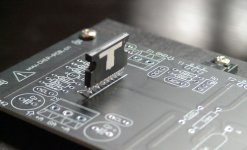
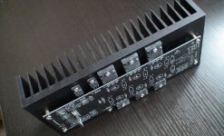
 The LME49810 as the core, one to three pairs of Toshiba output stages.
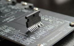
Hi,glennb said:
Greg as you probably know, hFEs on the spec sheet are meant to be a guide only. A real-life batch of transistors from a particular manufacturer tested at a load current of a few Amps on a heatsink might show hFE anywhere from 50 - 120.
Also, your example was good for an 8 Ohm resistive load, but for a speaker system load you should allow for impedance dips and V-I phase angle changes around the speaker resonances. The output transistors' peak current and average power dissipation should be calculated as if a 3-4 Ohm load existed, for an 8 Ohm nominal speaker system. There is a fair bit of leeway here because the low impedance loads only exist at some frequencies and the average long term power in music at these frequencies may not be significant.
Even with a 50mA drive capability from the '48910, its still not much good to directly drive a typical output transistor to achieve over about 25 Wrms output into 8 Ohms.
MOSFETs and Darlingtons are a different situation...
the peak current into a speaker can approach twice what is predicted using nominal impedance. I tend to assume that the minimum impedance for short term transient signals is half the Re of the driver.
On that basis an 8ohm speaker could present 3r0 to the amp and should not damage it nor activate the protection.
4ohm speakers could present 1r5 to 2r0 to the amplifier.
That is why I keep repeating that chipamps are not suitable for 4ohm speakers if you expect to get near maximum output.
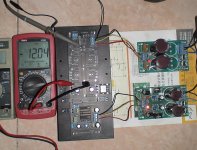
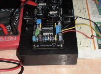
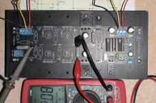
LME49810 Test
No.3
Passed the test and the actual hearing, the overall performance has improved over the LM4702. This benefit from the Slew Rate and mono design.
Testing the use of 2SC5200/2SA1930 (Fairchild Ver.), Hearing on the flu fluent, dynamic.
The overall impression that the LME49810 is a good chip.
No.3
Passed the test and the actual hearing, the overall performance has improved over the LM4702. This benefit from the Slew Rate and mono design.
Testing the use of 2SC5200/2SA1930 (Fairchild Ver.), Hearing on the flu fluent, dynamic.
The overall impression that the LME49810 is a good chip.
Attachments
Hi monkey29
Great to see you are developing a PCB for the LME49810 chip so soon.
Tony and I are very impressed with your work with the LM4702 and are very excited to try your LME49810
Board as soon as it is available.
I have built two LM4702 amps with my own design boards and Tony and I have built one each with yours.
Although they basically all sound the same, There are slight differences in the way they sound and it is hard to say exactly why.
I prefer not to say which ones sound the best until I have determined why.
I have a question! In the NS applications note AN-1490 for the LM4702 NS have specified a 15nf/1250v polypropylene capacitor across source and sink. I note you have used 100nf/100v “orange drop” polyester in your design and it is across the trimmer! I have moved the capacitor to the original NS position and replaced it with 15nf/300v mica (this is a big cap for a mica but I just happened to have some) and I am sure this improves the sound.
Why have NS specified such a high quality capacitor for this application?
Also would you consider developing a compact LME49810 board for just one pair of Darlington or MOSFET transistors without drivers and DC coupled throughout.
I know I should try and develop it myself but your boards, as so neat it’s hard to compete.
Keep up the good work.
Greg
VLSI said:Hi monkey29
I have a question! In the NS applications note AN-1490 for the LM4702 NS have specified a 15nf/1250v polypropylene capacitor across source and sink. I note you have used 100nf/100v “orange drop” polyester in your design and it is across the trimmer! I have moved the capacitor to the original NS position and replaced it with 15nf/300v mica (this is a big cap for a mica but I just happened to have some) and I am sure this improves the sound.
Leave the mica caps to the compensation circuitry and RF bypass on the input -- a high quality PP or PE cap across the VBE multiplier couples source and sink at audio frequencies -- The 15nF/1250V ECG cap is very, very low inductance -- you can also use a WIMA PP cap here. Digikey seems to be a preferred vendor for the Nat Semi folks and DK doesn't carry WIMA. Mica is not correct here -- fwiw, I found that 100nF across the VBE multiplier works just fine...
I have built the AN1490 amplifier with and without the 30pF mica from Source to Base of the VBE multiplier and can neither detect or measure a difference in performance.
With the LM4702 and LME49810 you can play around with the compensation capacitors to trade off stability vs slew rate...more to follow...stay tuned.
Re.
The LME49810 and My M-4702-F module, all have a good sense of hearing. Sound of performance , LME49810 slightly better, more details.
I think the voices of the description is more difficult. After listening to more, there will be further awareness.
Triodas said:Hello Monkey29,
My LME49810 samples will be delayed, so I can't do my tests.
What is sounding difference betwen LME49810 and LM4702?
Thanks.
The LME49810 and My M-4702-F module, all have a good sense of hearing. Sound of performance , LME49810 slightly better, more details.
I think the voices of the description is more difficult. After listening to more, there will be further awareness.
- Home
- Amplifiers
- Chip Amps
- LME49810 - a new cousin for LM4702