Hello All
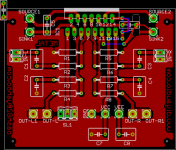
I will post a new modified PCB design for LM4702, I will modify the PS bypassing a little bit, so all guys be satisfied, and feel good about the PCB design, no problem.
Also I will work on the other PCBs for the power transistors to which I pointed out yesterday, (2SB1564/2SD1449), (MJL4281/MJL4302-MJE15034/MJE15035), (MJE11031/MJE11032).
I have read the datasheets for SAPs new transistors, and they have very good features, but I found this to be frustrating a little bit:
5. Destruction capacity of the built-in emitter resistor
The built-in resistor is fabricated with polysilicone on the chip for the SAP08P/N and a thick-film resistor is
used for the SAP10P/N and SAP15P/N. The latter, the thick-film resistor, has weaker destruction point in the Pc area (especially for large current flowing area) rather than that of the transistor chip itself.
This is subject to the area beyond Safe Operating Area (S.O.A).
However, under the evaluation like a short circuit test in which the current exceeds the guaranteed value, it
may cause the emitter resistor to be destroyed before the transistor itself is destroyed.
Consequently, the current value (or time) that operates the protection circuit is to be set at lower than that of discrete device configurations. In the application of car audio amplifiers, the same manners as the above need to be considered because the large current is flowed at low impedance.
In addition, once the transistor falls into thermal runaway due to a soldering failure to the external VR added between diodes or other failure manners, as the worst case, there may cause a resin crack or smoke emissions by flare up.
Flame retardant molding resin is used, and the material of the product is conformed to the most sever standard UL94V0.
However it is recommended that the careful consideration be given to a protection circuit, and the protection circuits should be provided appropriately in due course.
If the operating conditions are not to be matched to the ratings, it is also recommended that the E (Emitter resistor) terminal should be opened and the external emitter resistor should be added to the S (Sensing) terminal shown as below. (However this is not applicable to the SAP08P/N because a thin inner lead is used for S terminal.)
Looking from a cost-effective perspective, I don't think these transistors are best suited to this application in deed. What do you think guys ?
Russ White said:I am not sure what concerns you. Shorting just about output resistor beyond its rated power dissipation will kill it. Just don't short it.Or you could build an output protection circuit.
Still there are plent of good parts to choose.
Any audio diyer can easily short the output power transistors by mistake in deed, but I will try not to short them
Do you have any short protection circuits on mind russ...
metal said:Hello All
I will post a new modified PCB design for LM4702, I will modify the PS bypassing a little bit, so all guys be satisfied, and feel good about the PCB design, no problem.
Also I will work on the other PCBs for the power transistors to which I pointed out yesterday, (2SB1564/2SD1449), (MJL4281/MJL4302-MJE15034/MJE15035), (MJE11031/MJE11032).
I have read the datasheets for SAPs new transistors, and they have very good features, but I found this to be frustrating a little bit:
5. Destruction capacity of the built-in emitter resistor
The built-in resistor is fabricated with polysilicone on the chip for the SAP08P/N and a thick-film resistor is
used for the SAP10P/N and SAP15P/N. The latter, the thick-film resistor, has weaker destruction point in the Pc area (especially for large current flowing area) rather than that of the transistor chip itself.
This is subject to the area beyond Safe Operating Area (S.O.A).
However, under the evaluation like a short circuit test in which the current exceeds the guaranteed value, it
may cause the emitter resistor to be destroyed before the transistor itself is destroyed.
Consequently, the current value (or time) that operates the protection circuit is to be set at lower than that of discrete device configurations. In the application of car audio amplifiers, the same manners as the above need to be considered because the large current is flowed at low impedance.
In addition, once the transistor falls into thermal runaway due to a soldering failure to the external VR added between diodes or other failure manners, as the worst case, there may cause a resin crack or smoke emissions by flare up.
Flame retardant molding resin is used, and the material of the product is conformed to the most sever standard UL94V0.
However it is recommended that the careful consideration be given to a protection circuit, and the protection circuits should be provided appropriately in due course.
If the operating conditions are not to be matched to the ratings, it is also recommended that the E (Emitter resistor) terminal should be opened and the external emitter resistor should be added to the S (Sensing) terminal shown as below. (However this is not applicable to the SAP08P/N because a thin inner lead is used for S terminal.)
Looking from a cost-effective perspective, I don't think these transistors are best suited to this application in deed. What do you think guys ?
i wouldn't worry much about the built-in 0.22ohm resistors, what can be done is to add external resistors in series with the emiters, say another 0.22 then add more sap's in parallel to get a better SOA rating for the output stage! this is how i will do it when using the sap devices!
metal said:Hey demogorgon
Glad to hear from you, I do really care about your opinion, and other member opinions too, as you have a nice perspective for such matters Marius.
See ya
why, thanks, i'm almost blushing here i'm sitting
Russ White said:
Sorry to say so, but your first point is patently false, some LM3886 circuit can draw 15ma to 25ma at idle, yet good bypassing can make all the difference in the world, it is not just sound I am after either, it is also stability. Bypassing as optimally as possible is always the best choice, not that compromises don't sometimes have to be made.
As for you second point, any suitable power transistor you choose could be used. I don't make any assumptions on that.
I think you need to read me better, either that or i need to practis my english, as we think each other wrong, but trying to say, basically, the same thing.
bypassing as close as practical, not possible, and as good as practically possible. thats my view.
point two, the chip dosent need darlingtons after all?
i was under the impression that it did after reading the datasheet.
what will the effect of removing qmulti1 on the datasheet resoult in?
I was thinking this, with the resistors, were there to help counter thermal runaway?
-Marius
edit: metal i just ah a slight idea on how to drop one of the links:
but it has been decided one-chip-darlingtons are to be used, and the biaskiller transistors gone?
they can offcource be hardwierd on, but then the using of a pcb looses much of its advantages\usefullness over a p2p or a bread board.
Attachments
demogorgon said:
point two, the chip dosent need darlingtons after all?
i was under the impression that it did after reading the datasheet.
what will the effect of removing qmulti1 on the datasheet resoult in?
I was thinking this, with the resistors, were there to help counter thermal runaway?
If you use theramally compensated devices like SAP16 you do not need qmulti,, otherwise they should be included on the power device PCB.
Also you can easily make your own darlington pairs and use a wide range of devices.
My idea is to make the driver PCB as generic as possible by taking any output device dependancies off the driver board and moving them onto the power device board.
Cheers!
Russ
If you use theramally compensated devices like SAP16 you do not need qmulti,, otherwise they should be included on the power device PCB.
Using thermally compensated devices require the money to buy such.
I have under a dollar a day to live for, at least for another 15 days, so naturally i cant get those, though i can get conventional power transistors.
edit: just read that line closer, power device pcb?
gahh, hate building stuff out of 3-6 different boards when it could be done better on one.
Also you can easily make your own darlington pairs and use a wide range of devices.
not with the pcb as such i cant, then i'l be having to hardwire, and the pcb's usefullness is again limited.
besides, there isn't a very wide selection of thermally compensated BJT's around are there?
wich answers this:
My idea is to make the driver PCB as generic as possible by taking any output device dependancies off the driver board and moving them onto the power device board.
my view on thing
cheers
Marius
btw, forgot to say metal, nice pcb, i love the symetri
though it's not the one i'l need
demogorgon,
If you have a set of requirements you would like to see in a PCB I would be glad to see if I can accomodate you.
I chose the SAP16 simply because it has a great reputation, and it removes something like 6 components from the schematic.
You could build this amp with 2 SAP16P 2 SAP16N and the LM4702 for around $30 + passive component costs which are quite variable.
That seems pretty darned reasonable to me.
But I also understand living on a budget.
So give me your ideas.
Cheers!
Russ, This dialog turned out better than i had thought, good thing you are a diplomatic man
well, i'm trying to point this\these design\designs into a more intigrated solutions, thats based on logic and knowledge rather than the latest fashion on the forum
like mauro's 3886 amp. no BS, just a good design. no snake oil. no matter how cheap it comes
i'l have to sit down with pen and paper and make a scetch of what i envision, but not tonight. tomorrow.
oh, btw, something that cost you in the states 30bucks will cost me about 60 here up north. if not more.
there's a reason the wages up here are about twise as high as yours.
edit, not as in you, but rather all americans offcource.
gonna go try out Quake4 now. good evening to you all.
-marius out.
This discussion has led me to one clear and concise conclusion....I really need to finish my new speakers!
Seriously, both of these designs look pretty good so far! Personally I would like to see individual output boards as it allows for more flexibility where heatsinking is concerned (lets face it that will be the biggest cost). It also allows for more flexibility in the chassis design and layout. This will also allow you the flexibility to experiment with different output transistors etc.
I look forward to seeing what happens with this design. Has anyone given some thought to a PSU for these????
G.
Hello
demogorgon:
If I am not wrong, you need to see two transistors (MJE15034/5) on the LM4702 PCB in order to hardwire (MJL4281/MJL4302) directly, not forgetting the addition of the bias transistor....
I already said, I will make it versatle, and satisfying to all valuable members interseted in this project. I will try to do what is mentioned above. I will also try to keep it single sided....
In this one, I have made the small signal tracks shorter as much as possible, and moved the PS capacitors in order to allow using a connector for the PS. I added the mute resistor also which I completely forgot, now its on the PCB, along with another connector for +5 Volts
Attachments
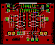
and still as beautifully symetric
I'l whip up the scetch i promised now, and be back shortly.
Oh, and GCollier, an output board would not be as flexible as transistors connected only using wiers from the board.
wish i could have shown you a pic, but i have non available right now, but i'l be back though.
-Marius
I'l whip up the scetch i promised now, and be back shortly.
Oh, and GCollier, an output board would not be as flexible as transistors connected only using wiers from the board.
wish i could have shown you a pic, but i have non available right now, but i'l be back though.
-Marius
Hello demogorgon
Glad to see that you like it demogorgon, I always try to do the best I can...
I will be waiting for your sketch
Gcollier:
Hey man, why hurry, as you can see, not all the members interested in this project are completely satisfied with this PCB design, so, late results, are better than nothing, Glad your up here now
- Status
- This old topic is closed. If you want to reopen this topic, contact a moderator using the "Report Post" button.
- Home
- Amplifiers
- Chip Amps
- Lm4702