Hello
I might get some of these chips !!
Upon this & that, I will start designing a PCB for this nice thingy, I will post the design of the PCB asking for your opinions and suggestions to make it as blameless PCB design as possible for the LM4702.
Just wish me good luck...
I might get some of these chips !!
Upon this & that, I will start designing a PCB for this nice thingy, I will post the design of the PCB asking for your opinions and suggestions to make it as blameless PCB design as possible for the LM4702.
Just wish me good luck...
")
I was just thinking, if these are going to be like $5 or $6 it really wouldn't be worth it.
IMO, if it's only replacing the first and second stage of a typical lin amplifier, then it's only replacing a few resistors and maybe 5 transistors, which would cost you ,mmm, maybe a dollar.
I could be wrong but I don't think I'd pay for something that simple to make.
The're like a 200v opamp with no output stage, and while .005% d is nice it's not hard to attain with discrete componets.
Just a thought.
Hello
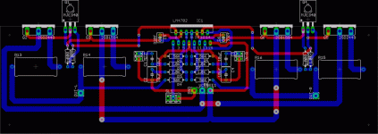
I am designing the whole thingy in deed, so the PCB will contain one LM4702, two driver transistors and four output power transistors, also the "diode" transistor...
I 've concluded that it will be a better idea to be able to change the driver transistors, that will yeild the flexibility of having as many output transistors as the designer wants. For now, I will only include four output power trnsistors.
I have finished designing the library of LM4702, I will also design a library for the output power transistors, I will have MJL series.
For now, here is the library for LM4702, guys who use Eagle and are interested in this project, shall see this library and make sure its absolutely mistake free...
I also might omit the driver transistors and use power darlington instead, I am still confused on which one to go with...
Good LM4702 day !
Attachments
Hello
I have found these complementary darlington output power transistors to be a really good choice. I don't know if they are available in my country and other countries, but I will try to find out tomorrow.
MJ11031/2 complementary darlington output power transistors are rated at much higher power, but they are intended for general purpose audio power amplifiers, I don't assume they will be as good as those transistors that have transition frequency of 30MHz....
2SD2449
2SB1594
Let me know if there are any other suggestions for the darlington output power transistors that are as excellent as these and have transition frequency of 25MHz or higher, but rated at higher operating voltage and power.....
Member
Joined 2004
Member
Joined 2004
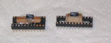
SMD technique
John:I use the following technique for soldering SMD chips to an IC socket.I glue a small piece of wood to the base of an IC socket,I then use a small dab of hot melt glue under the chip and then secure it on top.I then solder 30awg wires to the IC socket,I then carefully align the wires to the chip and use solder paste to solder.I have successfully done several dozen chips with this method and have not lost one yet!....
Bob C.
Attachments
Hello
I don't think its a matter of 4 to 5 transistors in deed, this IC, has current mirrors for the constant current consumption, which lowers the THD very much, also a thermal shut down feature, which also need more transistors, you start counting.....
The most important thing is the neat looking of the amplifier, and the high performance at the same time, that can be obtained using this IC...
The PCB I posted is just a prototype, I am still working on it, and will make it single sided if I can, I will also place LM4702 on a separate PCB, and the output stage on another PCB, the output stage PCB will have many verions, I mean there will be one PCB for LM4702, and two or three PCBs for the output satge from which you can select one that satisfies your transistors....according to the power transistors used....TO-3, TO3P...Darlington.....with drivers......etc...
Member
Joined 2004
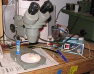
SMD soldering
Hello Wes-Ninja:I first solder all of the wires into the IC socket,I use ic sockets with gold or silver plated round holes.I solder one wire at a time,a small amount of solder paste is applied to each pin followed by soldering with the 30 watt soldering iron.I do hold the wire to the pin with a fine point tweezer.
I can complete a 16 pin device in less than 1/2 hour.
Regards Bob C.
Very Nice
Metal, that looks very nice. Of cource i'm no expert, just a pleb....... But looks very good, you are very talented, i only wish i had the ability to do this. I have ordered some chips as samples ,but i wonder how long they will take to arrive. That is a very good idea to enable people to decide on outputs as some of us might not be able to get what we really want and this gives us a few more options.... good thinking
Metal, that looks very nice. Of cource i'm no expert, just a pleb....... But looks very good, you are very talented, i only wish i had the ability to do this. I have ordered some chips as samples ,but i wonder how long they will take to arrive. That is a very good idea to enable people to decide on outputs as some of us might not be able to get what we really want and this gives us a few more options.... good thinking
No worries mate
I just hope i can keep up with this thread. It looks very interesting, but being married and completely under the thumb...hehehe. I have completed just one gainclone, but started another..... man if my mrs found out i was looking at more projects instead of working on the house.....blood will be spilt....hehe. I think I'll have to start bargaining with her, she can get her hair done this month if i can buy another transformer......sounds good to me
I just hope i can keep up with this thread. It looks very interesting, but being married and completely under the thumb...hehehe. I have completed just one gainclone, but started another..... man if my mrs found out i was looking at more projects instead of working on the house.....blood will be spilt....hehe. I think I'll have to start bargaining with her, she can get her hair done this month if i can buy another transformer......sounds good to me
Bob -- thanks!
I'll have to add that one to my book of tricks.
Once upon a time, I had to do something similar, but on a larger scale -- replace a wide DIP with a skinny DIP. I was replacing a defective SRAM chip and couldn't find a wide DIP of the right type.
I ground down an old EPROM, removed the die, then bent the pins straight on the skinny DIP and finished the connections to the EPROMs pins with 22awg solid copper wire. I also had to add an extra decoupling capacitor.
Wes
- Status
- This old topic is closed. If you want to reopen this topic, contact a moderator using the "Report Post" button.
- Home
- Amplifiers
- Chip Amps
- Lm4702