Re: Re: Re: Re: LM4562 (dual op-amp) simple preamplifier
Yes, I still have about 10 of PCB’s for this project.
Jumpers are on the bottom side of this PCB")
wim said:Thanks for answering veteran.
I hope to hear from you if you have (a) board(s) availabel
Yes, I still have about 10 of PCB’s for this project.
carlmart said:
The feedback capacitors (C3/C7) do not seem to be jumpered. But at least it can be easily done in the assembly.
Jumpers are on the bottom side of this PCB
Hi,
If I make this preamp;
- Should I put the pot (100K log) at the input or output?
- May I split the ouput via two series resistor, and connect one of this outputs to my LM4702 amp (it has 6K8 input impedence) and the other to a simple LT1210 headphone amp (with how much input resistance?) that makes any problem?
Thx..
Hi Dxv,
if you fit a 100k pot at the output, you will have an output impedance of 25k when volume is set to -6db.
That will not work into most equipment.
You must buffer the volume control or fit it at the input of the next stage.
If you do fit it to the next stage, then that stage must be designed to tolerate a variable source impedance that can range from zero ohms to 25kohms (0r0<=Rs<=25k). Are you ready for that design process?
Hi Andrew,
I am not sure that I can design a stage like that...
So its better to make new design with two stages like that;
http://sound.westhost.com/project88.htm
I guess I can couple both my LM4702 amp and LT1210 headamp to this circuits output via a series 100R like resistor and a MKP cap..
What do you think?
AndrewT said:if you fit a 100k pot at the output, you will have an output impedance of 25k when volume is set to -6db.
That will not work into most equipment.
........... next stage, then that stage must be designed to tolerate a variable source impedance that can range from zero ohms to 25kohms (0r0<=Rs<=25k). Are you ready for that design process?
then scrap the 100k pot proposal and adopt a 5k or 10k pot. Many circuits with a bit of help from you, the designer, can manage much better with a low source impedance.Dxvideo said:I am not sure that I can design a stage like that......
Dxvideo said:If I make this preamp;
- Should I put the pot (100K log) at the input or output?
You should put the pot at the input, not at the output. The preamp will isolate the pot from the power amp. You can use a buffer for that, with a 1:1 gain, but any line preamp like this one will do that.
This is the way most integrated amps are designed, sometimes having one more stage before the line preamp for phono.
You can also use a pot with no gain and no preamp/buffer, which is called passive preamp. But results will depend on the power amp's impedance.
- May I split the ouput via two series resistor, and connect one of this outputs to my LM4702 amp (it has 6K8 input impedence) and the other to a simple LT1210 headphone amp (with how much input resistance?) that makes any problem?
As the preamp has low impedance output, there shouldn't be any trouble in feeding both the power amp and the headphone amp. The latter probably has an input resistor, probably 47K or so, doesn't it? That should be fine.
Feeding low impedance into high impedance, or high impedance into low impedance is no problem. Problem is when low into low, or high into high.
The speaker amp has only 6K8 input resistance, and the future LT1210 headamp will have 47K...
However,
I found a solution,
However,
I found a solution,
What do you say?An idea;
May I use LT1210 instead of LM4562 in this circuit (of course a pair of LT1210). In this case I wil have both headphone amp and a preamp for speaker amp with a simple circuit...
Any comparison you made; LM4562 vs LT1210?
Dxvideo said:The speaker amp has only 6K8 input resistance, and the future LT1210 headamp will have 47K...
It's OK. You can feed them both from this preamp
What do you say?
You mean using the LT1210 to feed headphones and power amp?
Don't do that. Use a line preamp, with an LM 4562 or LT1210 chip, and feed power amp and another amp for the headphones. Use a level pot in the headphone's amp feedback.
Ok. I see.
You say LT1210 and LM4562 have not much difference on sound. However its better to use dedicated op-amps for headphone and line level outputs.
However, should I use common inputs for them, means they will be connected directly to the input together? In this case the input impedance will be paralelled on preamp and headphone inputs, so there may flow input bias current to eachothers input from the other. Is that true?
Thx..
Yes, the input offset currents will interact if neither are DC blocked with an input cap.Dxvideo said:....... In this case the input impedance will be paralelled on preamp and headphone inputs, so there may flow input bias current to eachothers input from the other. Is that true?
Most builders forget this and they seem oblivious to the problem.
It may be that it can be ignored with many set ups, but if you're using different opamps then that could be a worse situation.
Dxvideo said:You say LT1210 and LM4562 have not much difference on sound.
Whether they sound different or not I don't know. The sound of chips is something which everyone should judge by himself.
I haven't compared the specs either. Things like noise, slew rate and bandwidth influence how they will sound. That is up to you.
However its better to use dedicated op-amps for headphone and line level outputs.
You should separate the line amp chip from the headphone amp chip, and put a pot on the latter.
However, should I use common inputs for them, means they will be connected directly to the input together?
There are no common inputs: the heaphone amp comes after the line amp. The inputs are all connected to the line amp.
The order would be inputs, selector switch, volume pot, balance pot, line amp. From it you connect to power amp and headphone amp.
After the selector you may add tape-outputs, which should be buffered.
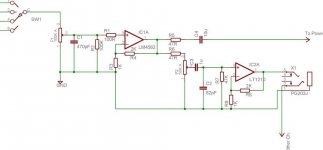
Dxvideo said:You mean simply that;
Is it?
Yes, with some corrections.
1) It might be better adding a film cap after P1, if you have pot noises.
2) Put things in this order before IC1A: pot 1, cap, R1, R2, C1.
3) Put C4 just after IC1A. Then R4 to power amp, and R6 to headphone amp increased to 1K.
4) Don't put the headphone pot there or it will interact with the power amp input. Put a pot in IC2A feedback instead of R8.
5) If you don't want above you will have to add a buffer before IC2A, and put the input pot after it.
Instead of all those;
I can remove the P2. If I already make adjustment before the preamp then a headphone volume adjusting is unnecessary I think.
So as a conclusion;
I will split the output of LM4562 via two 100R resistor plus DC blockings. One of these goes to the power amp and the other to headphone amp. But if I put the DC blocking before current limiting resistors (100R) then the input bias currents will flow from one to the other (as mentioned before), then I think I must put them after the splitting. Am I right?
And for the other DC blocking on preamp input that you adviced, it looks necessary to protect LM4562 from input based DC offsets. However, so many capacitors on signal path creates a little more distortion.. Do you agree with me?
Thx..
Dxvideo said:Instead of all those;
I can remove the P2. If I already make adjustment before the preamp then a headphone volume adjusting is unnecessary I think.
If you have a separate headphone amp, it's useful to put a separate pot for it. If not you can always feed the headphone from the power amp itself, properly protected with a 100 ohm resistor.
But if I put the DC blocking before current limiting resistors (100R) then the input bias currents will flow from one to the other (as mentioned before), then I think I must put them after the splitting. Am I right?
First of all, if you already have a blocking cap at the power amp input, you won't need another one, so you could eliminate C4. That cap would block any DC bias currents.
And for the other DC blocking on preamp input that you adviced, it looks necessary to protect LM4562 from input based DC offsets. However, so many capacitors on signal path creates a little more distortion.. Do you agree with me?
Certainly so. That's why I said to check if you already have a blocking cap, preserve that and cut the other. The ideal thing is for you to use just that one cap, at the power amp's input, along the whole chain.
So you have to check if your sources output DC offset and block those that do. Or use servos to correct the offset.
Ok,
Thats the situation;
I have a LM4702 + lateral MOSFET amplifier. It has a 6K8 input impedance (a bit low!) and NO INPUT CAP at the moment. It has a really huge and ugly enclosure and WAF doesnt accept it on the TV stand. So I will put it behind of the stand. However in this case the control operations (on/off, volume, input selecting etc.) get impossible.
Then I thought, it will be a solution to make a seperated tiny preamp enclosure (and also a handsome one). And if I will have a seperated enclosure then why wouldnt I put a headphone amp inside of it...
This is the history. So what can you advice on that?
Thx again...
Very easy.
First of all add a blocking capacitor at the amp input, film type if possible. What are the resistors & caps at the amp input?
Second you can use a separate box, better looking, to house the preamp, inputs, switch, supply, etc. and put it wherever you want.
As the preamp's output is low impedance there won't be any problem to use a 2 or 3 meter cable to the power amp.
And use a separate headphone amp, with its own lovel pot wired as I said.
It won't be tiny though, particularly because of the supply.
- Status
- This old topic is closed. If you want to reopen this topic, contact a moderator using the "Report Post" button.
- Home
- Amplifiers
- Chip Amps
- LM4562 (dual op-amp) simple preamplifier