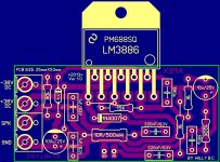
Good afternoon, Mark! Thanks for the information about the P3! About the correct voltage for the 16 ohm hard for me to say. Speakers normally work with tube amplifiers on 2A3, 300B, and transistor McIntosh 2505 (50W per channel) Still relatively acoustics. Why am I interested in this amp ... Before this amplifier LM3886, I built for a friend exactly the same amplifier LM3886. It was built with a tube preamp ECC88 in one case. And then the problems described above was not! It is played with this acoustics fine. Film Capacitors 50uf really big, and they are located on the bus connected to the contacts of the circuit. But! There are also small capacitors WIMA 50uf to 50v. My friend owes it. For them, too, have to hunt. There used to be on the Mauser, buddy bought on eBay.They can be placed directly on the board.
Paper oil - Russian MBGO-2. If its 100V and 160V (they are more difficult to find than 500V and 630v, but possible) ratings 3uf, 4uf, 5uf, or even 10uf are compact enough, and with them no problem. The terminals are soldered directly to the board space.
Paper oil - Russian MBGO-2. If its 100V and 160V (they are more difficult to find than 500V and 630v, but possible) ratings 3uf, 4uf, 5uf, or even 10uf are compact enough, and with them no problem. The terminals are soldered directly to the board space.
Last edited:
C1 and C2 supply current to the chip. The chip, capacitors, leads and traces have inductance. The inductance reduces the ability of the capacitor to supply current to the chip. The goal is to use low inductance capacitors and to place them close to the chip.
The Ground, feedback loop and the Zobel also need to be designed for low inductance.
Here are some examples. Post #1 and #30 demonstrate the improvements that can be achieved by a good layout.
http://www.diyaudio.com/forums/chip-amps/252436-lm3886-pcb-vs-point-point-data.html#post3845470
The Ground, feedback loop and the Zobel also need to be designed for low inductance.
Here are some examples. Post #1 and #30 demonstrate the improvements that can be achieved by a good layout.
http://www.diyaudio.com/forums/chip-amps/252436-lm3886-pcb-vs-point-point-data.html#post3845470
Dear Mr. Apex sir,
I have following queries.
1. What should be the wattage of the zener diode?
2. Instead of 1N4004, can we use 1N4007?
3. What is the wattage of the resistors (1K, 10K, 15K and 100K)?
4. what type of capacitors should we use for 1uF and 220nF? metallised PET/PEN is ok?
regards
Prasi
I have following queries.
1. What should be the wattage of the zener diode?
2. Instead of 1N4004, can we use 1N4007?
3. What is the wattage of the resistors (1K, 10K, 15K and 100K)?
4. what type of capacitors should we use for 1uF and 220nF? metallised PET/PEN is ok?
regards
Prasi
Dear Mr. Apex sir,
I have following queries.
1. What should be the wattage of the zener diode?
2. Instead of 1N4004, can we use 1N4007?
3. What is the wattage of the resistors (1K, 10K, 15K and 100K)?
4. what type of capacitors should we use for 1uF and 220nF? metallised PET/PEN is ok?
regards
Prasi
Resistors are 0.25W, zener is 0.5W and 1N4007 can be use,
Regards
Attachments
Last edited:
Oh... Thanks Mr. Apex for the quick reply. One more question, with reference to post no. 1 of this thread, Can PSU circuit (4700uF caps and rectifier) be integrated on the same PCB as that of LM3886? I would also like to integrate the sub crossover given in you mic, line, eq " thread make it as a sub plate amplifier, will it work? are there any foreseeable design issues? I will make a pcb in eagle and post it for everyone's' approval.
PS: SOrry Mr. Whitney I got my reply.
PS: SOrry Mr. Whitney I got my reply.
H
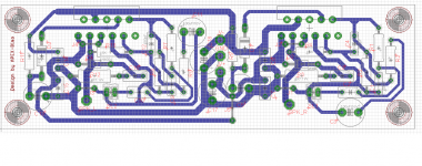
See my PCB for the power supply
Hi Audisoul,
DO you have above pcb with +/- 15v o/p for tone control instear of +12v amd +5v?
reg
prasi
Hi Bimo and others,
I built apex gainclone amp based on the pcb created by bimo (post 231) . when i connected the input, the sound is very distorted on both speakers. when I connect a wire from signal ground to main chassis ground, the sound is nice but coming from only one speaker. I tried a lot of things, but result is same. can anyone help me identify the problem?
regards
prasi
Attachments
")
Hello drahcir,
Thanks for the reply. I have checked all connections and cap placements they are as per the PCB. diodes are also as per layout. I know that the signal ground and power ground already connected on the PCB through a trace. The funny thing is, when I do not connect an additional ground wire from signal ground to main chassis ground, the sound comes from both speakers, but is very distorted. Does this mean that the both IC's are functional. However, when I connect an additional wire from signal in ground to main chassis ground, the sound improves but comes from only one speaker.
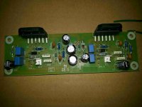
The IC's are from TI samples. coud there be a grounding issue? I am attaching here with the layout of the PCB created by Bimo (post # 231).
regards
prasi
Thanks for the reply. I have checked all connections and cap placements they are as per the PCB. diodes are also as per layout. I know that the signal ground and power ground already connected on the PCB through a trace. The funny thing is, when I do not connect an additional ground wire from signal ground to main chassis ground, the sound comes from both speakers, but is very distorted. Does this mean that the both IC's are functional. However, when I connect an additional wire from signal in ground to main chassis ground, the sound improves but comes from only one speaker.
The IC's are from TI samples. coud there be a grounding issue? I am attaching here with the layout of the PCB created by Bimo (post # 231).
regards
prasi
Attachments
Hi drahcir,
Speaker SPK_L and SPK R are the speaker positive. Speaker return wires from both channel go to the main star ground on chassis. Here is the set up.
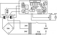
1. Transformer : 300 VA with single 24-024 out put
2. PSU : 10 amp bridge rectifier with 4x 4700 caps
3. stereo AMP as above in post # 437.
right now I am not using any tone control. signal i/p is directly connected to the amplifier PCB at SL1 and SL2.
The PSU is commercial and hence do not have its lay out file.
The wiring scheme is as follows.
1. Power comes in through an IEC 3 pin inlet.
2 . Both Line and neutral are connected to a switch but AC line goes through a fuse .
3. Transformer is connected at the switch outlet.
4. transformer out put 24-0-24 is connected to the PSU
5. 32-0-32 from the PSU is connected to the amplifier PCB at V+ , GND and V-.
6. SPK_L and SPK_R is connected to right and left speaker positive.
7. Signal in and signal gound is connected to the amp PCB at SL1 and SL2 (see post# 437).
8. speaker returns from both channels (back wire) is coonected to the chassis ground (star)
9. A wire from chassis ground is connected to the earth pin of the power inlet.
where I am making a mistake ? or what could be isssues with grounding?
regards
Prasi
Speaker SPK_L and SPK R are the speaker positive. Speaker return wires from both channel go to the main star ground on chassis. Here is the set up.
1. Transformer : 300 VA with single 24-024 out put
2. PSU : 10 amp bridge rectifier with 4x 4700 caps
3. stereo AMP as above in post # 437.
right now I am not using any tone control. signal i/p is directly connected to the amplifier PCB at SL1 and SL2.
The PSU is commercial and hence do not have its lay out file.
The wiring scheme is as follows.
1. Power comes in through an IEC 3 pin inlet.
2 . Both Line and neutral are connected to a switch but AC line goes through a fuse .
3. Transformer is connected at the switch outlet.
4. transformer out put 24-0-24 is connected to the PSU
5. 32-0-32 from the PSU is connected to the amplifier PCB at V+ , GND and V-.
6. SPK_L and SPK_R is connected to right and left speaker positive.
7. Signal in and signal gound is connected to the amp PCB at SL1 and SL2 (see post# 437).
8. speaker returns from both channels (back wire) is coonected to the chassis ground (star)
9. A wire from chassis ground is connected to the earth pin of the power inlet.
where I am making a mistake ? or what could be isssues with grounding?
regards
Prasi
Hi All,
Problem solved.
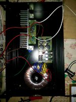
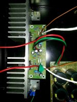
It was a mistake from my side. I had not connected the J5 (jumper) on the PCB. It is such a foolish mistake and is obvious in my own post #433 (center image). There was no V+ supply on left channel because of this.
After connecting the J5 and improving the grounding scheme, The amp is churning out amazing sound with no pop at start-up and without any distortion.
Improved grounding scheme is as follows.
1. A cable from chassis ground point (star) goes to earth pin and this connection is permanent.
2. speaker returns and amp ground wire go to the PSU ground
3. A wire from PSU ground goes to the star ground
does anyone have any comments on the above grounding scheme? is it safe?
it seems to be working fine with no hum. the amp is very quiet when the source is connected but without any music being played.
Also I measured the DC offset (voltage between speaker positive and chassis star ground) when speakers are connected without any music being played. It is around 10mV and 11mV on left and right channels.
regards
prasi
Problem solved.
It was a mistake from my side. I had not connected the J5 (jumper) on the PCB. It is such a foolish mistake and is obvious in my own post #433 (center image). There was no V+ supply on left channel because of this.
After connecting the J5 and improving the grounding scheme, The amp is churning out amazing sound with no pop at start-up and without any distortion.
Improved grounding scheme is as follows.
1. A cable from chassis ground point (star) goes to earth pin and this connection is permanent.
2. speaker returns and amp ground wire go to the PSU ground
3. A wire from PSU ground goes to the star ground
does anyone have any comments on the above grounding scheme? is it safe?
it seems to be working fine with no hum. the amp is very quiet when the source is connected but without any music being played.
Also I measured the DC offset (voltage between speaker positive and chassis star ground) when speakers are connected without any music being played. It is around 10mV and 11mV on left and right channels.
regards
prasi
- Home
- Amplifiers
- Chip Amps
- LM3886 Schematics + PCB