roadkill said:Madhu,
Go to Om Electronics (SP Road, third shop), give him a laser print of your layout (on A4 copier paper), he will quote a price (for PCBs of the size we're talking about, it's usually less than Rs. 100), pay him, get an order slip. Come back after a few days, show him the slip, collect your PCBs. EasyI tried the toner transfer method, results were quite shabby. Make sure you ask for a Glass Epoxy PCB. Phenolic is not worth the 10-15 rupee savings.
Also, the price you've mentioned is normal for a 750VA toroid. A 750VA E-I will cost a LOT more than Rs. 250 (close to 1k, I guess). For 250, you'd probably get a 250-300VA transformer if you buy it readymade. A custom wound transformer (try Universal Transformers, opposite Vishal Electronics), this price will get you a 225VA transformer.
I asked Om Electronics' proprietor about the PCB process. He said the laser prints are used to make films, which are then used to make a silkscreen. He then squeezes etch-resist ink onto a bare PCB and etches it. Naturally, the quality is nowhere nearly as good as a true photo-etched PCB, but it's good enough
Hi all,
roadkill, i went to om electronics and talked to suraj, the propreitor, he said that he would take 3 days for delivery. i didnt bother to ask him about the pcb process though.
anyway, the transformer price; it was quoted by a friend of mine. he has a coil winding setup and he said he would be able to do it for me. however, he asked me for the design and i am left in the dark. could you people point me out on how to design E-I core transformers??
so you say making pcbs at home is not worth the effort?? if it is, then it hurts my DIY spirit a great deal.
thanks for the suggestions and hoping for more....
Cheers,
Madhu.
tcpip said:I also have another schematic for a finished non-inv amp for the LM3886, from Elektor. In that schematic, they've handled the mute pin too, so one can simply pick up the resistor values based on what they've put in it. (They've put in the option for a mute switch, which I don't intend to use.... I'll just keep the circuit permanently "un-muted" when I design the PCB.)
I have this article in PDF format, in case you want me to mail it to you. It's a one-page thing with schematic and PCB layout.
Hi all,
I digged around on the internet some more after Tarun mailed me the above pdf; and i found one more elektor article, dated july-august 1998, FOR the 3886... however, the schematic and the pcb layout resemble (to a Mechanical engg. eye... ) the one in the above article... dunno the difference... you guys have a look at it..
just send across a mail to me.. ill mail it to you... by the way, is it ok if i just post the link to the file here??
Cheers,
Madhu.
I got a custom-wound 600VA E+I done for Rs.2750. I don't think these guys (Disco Winding Works on L.Road here) are inexpensive, but I think his transfies are up to spec (very low voltage drop at heavy loads, etc). This was for 25-0-25V, 12A per rail. Guru in Delhi sells ready-made E+I transformers. They sell a 26-0-26V, 5A transfy for Rs.550. That's about 250VA, and they're much cheaper than Disco of L.Road, but I suspect their load regulation will be worse.saltnpeppah said:Well, I got a quote of Rs. 2300.00 () for a 750VA toroidal tranformer; but on the other hand, a local manufacturer is quoting Rs 250.00 for an E-I core... its not exactly 1:10; but close to it.
BTW, my 600VA transformer will power a parallel array of 10 Gainclones. What kind of humungous setup are you planning to build with a 750VA transfy?
I don't know why Indian diyers in big cities make their own PCBs, unless (i) they're in a tearing hurry for some emergency work, or (ii) they enjoy the process. Neither of these applies to me. And making my own PCBs will usually result in much worse quality of work than what these small professional workshops do, and of course I save time, huge amounts of capital investment, and I can do things like solder masking which no home-brew PCB maker seems to do. So why don't you take Roadkill's advice and try getting the PCB made from a professional source?By the way, what method do you guys use to fabricate PCBs?? i tried to use the toner transfer method with limited results..
If you want to get them made from Bombay, there are places which will take all your datafiles by email, and courier the finished PCB to you. Please start reading from here and read through all the posts related to PCB making. There's more information here than any diyer needs to know, about Indian PCB making options.
In Eagle, you can set the "isolate" parameter of each polygon separately. I always set mine to 16mil, so I guess I'm already doing what you've pointed out. Just use "change isolate", select the value you want, and click on any of the wires of the polygon. You don't need to go into "Net Classes."roadkill said:Nice layout, here are some points:
- Either manually insert some space between the polygons for the ground plane and power planes, or use Eagle's "Net Classes" command to assign a clearance of more than 15 mils. The planes, if they're so close, will cause problems due to solder bridging, etc.
And solder bridging doesn't pose a problem for me because I get my PCBs solder masked.
The internal hookup wire for the speaker connections doesn't need to be any heavier gauge than the supply rail wires, and one can even use solid core if one wants. So, within the chassis, I intend to use any suitable thick stranded/solid wire for speaker connections, and one wire would come from the banana socket to the power-star-ground, and another piece would connect the PCB's power ground (marked GND) to the same star ground. I'm not sure they'll lift off the board due to their weight... they're short pieces of thick copper wire. They don't need to be 300 strands.
- How are you going to connect the speaker wire? If you just solder it to a pad, the joint will eventually either break or cause the pad to lift off the board, since the wire used will be heavy gauge.
I've not used the default pad sizes which come in Eagle. I have standardised on larger pad sizes, by going into Eagle's "DRC" function, and changing the minimum restring radius. Eagle comes with a default minimum restring radius of 10mil for pads and 8mil for vias. I use at least 18mil. I've been using it regularly, and my PCB making workshop too thinks that they're large enough. I've faced no problems.
- The pad dimensions you have used are more suited to a PTH board. If you use similar pads for a single sided board, the adhesion will be very poor, and the pads will tend to lift off easily. Usually, octagonal, elongated pads are used for single-sided boards.
And I certainly don't see any need to use elongated pads for all components in general. Are you specifically referring to the pads for the amp chip? Well, in that case, I started out with elongated, but then changed to circular (maybe I'll make them octagonal, I don't know) because elongated was taking up too much space between the rows of pins.
Interesting. I can see see your point. None of the gainclone PCBs I've seen on this forum have done what you're suggesting, but at least I can see the logic behind it. Let me see what I do. Your suggestion seems particularly appealing because there will be a few metres of distance between my bridge and the amp PCB, and putting some filter caps near the rectifier seems like a good thing to do.
- I'd advise you to use large filter caps close to the bridge rectifier. It may sound like paranoia, but the charging/discharging current into the filter caps will cause EMI, esp. for bridge rectifiers without snubber caps. Keep the smaller caps (220u or 470u) on the board, for local decoupling.
Interesting. When I'd made my earlier layout, I was told by friends that I should put thermals because otherwise they make soldering difficult. But for very high-current pads (like the chip amp here), I think your suggestion makes sense. I'll probably revert to "change thermals off" in Eagle.
- Disable thermals for the various planes being used. They will limit the current flow very badly.
Not to speak on behalf of Brian, but my Eagle 4.11 does rounded bends for tracks and polygon edges. The earlier Eagle 4.09 didn't do this.Brian, What PCB software are you using? I hope there's a freeware version available, since it can do rounded bends and polygon edges!
This is how Balaji Hertz (Mr.Subramaniam of Bombay) does it too. Like Om, he too prints using etch-resist ink through his silkscreens onto the copper-clad board. You can get 12mil tracks and you can easily pass one track between two legs of a DIP IC. You can't easily get 8mil tracks, and you can't usually pass two tracks between DIP IC legs. On the whole, for audio, I think one doesn't need anything better. Of course, if you get your films made directly on a Gerber photoplotter instead of via laserprint->photofilm, you'll see that finer details are possible using the same silk screen process. The limitation is in the initial film-making more than the silk screen, I think.I asked Om Electronics' proprietor about the PCB process. He said the laser prints are used to make films, which are then used to make a silkscreen. He then squeezes etch-resist ink onto a bare PCB and etches it. Naturally, the quality is nowhere nearly as good as a true photo-etched PCB, but it's good enough
Forget your friend, because he appears inexperienced in the specific area of transfies. Go to a shop which either sells ready-made transfies, or go to a winding company which regularly makes custom-wound transfies. There are many all over the place, and you will not need to pay prices as high as I paid to Disco Winding here. There are some design parameters to be taken into account when deciding the size of the E+I core, depending on the VA rating, current flow, and voltages used. But any transfy winding shop will do it without problems in about one minute. When I place an order with Disco, they go back to their PC, feed in my VA ratings and voltages into their software, and come back a minute later with the size of the core, overall dimensions, and therefore, pricing. It's that simple for a shop which regularly makes transformers. If your friend can't do this, go somewhere else.saltnpeppah said:however, he asked me for the design and i am left in the dark. could you people point me out on how to design E-I core transformers??
I guess you must've noticed that this is a "diy audio" site, not a "diy pcb" site. We use a lot of things which we don't create ourselves. For instance, we all use eCAD software which we haven't written ourselves. We also don't hand-craft our own capacitors.so you say making pcbs at home is not worth the effort?? if it is, then it hurts my DIY spirit a great deal.
No one will stop you, but just don't be very surprised if not too many others show much enthusiasm for your line of interest. There is no difference between the LM3886 and LM3876, other than an extra connection in the LM3886 for -Vcc, I think. The article I'd sent you caters to both the LM3876 and LM3886, where one jumper for this -Vcc is optional for the '76, but is needed for the '86.saltnpeppah said:I digged around on the internet some more after Tarun mailed me the above pdf; and i found one more elektor article, dated july-august 1998, FOR the 3886... however, the schematic and the pcb layout resemble (to a Mechanical engg. eye... ) the one in the above article... dunno the difference... you guys have a look at it..
How thick does internal hookup wire need to be?
And what's interesting is that this crowd is going for a no-compromise high-end build project, where they'd go for the thickest, lowest-impedance wire that they'd think would make a difference.
I got some interesting data points about what others are talking about regarding wire gauge sizes, when they're building no-compromise Gainclones. See this post where a reader asks what gauge of internal hookup wire to use, and Brian says 18AWG should be fine for everything. This includes supply rails and speaker output lead. I don't think 18AWG wire will rip itself off a reasonable-sized solder pad easily, do you?roadkill said:
- How are you going to connect the speaker wire? If you just solder it to a pad, the joint will eventually either break or cause the pad to lift off the board, since the wire used will be heavy gauge.
And what's interesting is that this crowd is going for a no-compromise high-end build project, where they'd go for the thickest, lowest-impedance wire that they'd think would make a difference.
Madhu,
If you want a good source for E-I transformers, it's Universal Transformers on SP Road. There's also Miracle Transformers (www.toridal.com), who make toroid core trannies. Use their website to choose a model, then email them for a quote. They charged me ~1200 for a 225VA (dual 25 volt windings @ 4.5A each), couriered it to me within a week. Good stuff!
I echo Tarun's comment, it's really not worth making your own PCBs. If we could get presensitized boards, that's a different story.
Tarun,
The Disco Winding Works quotes seem a bit high. Then again, the transformers from Universal sag by about a volt at full load.
Yeah, the isolate option's better, coz then the DRC wont complain as much.
If you have a temp controlled iron, set it to a higher temp (400 degrees works for me) when you're working on pads which go to a plane.
Eagle 4.11... ok, now I'm convinced enough to download it.
If you want a good source for E-I transformers, it's Universal Transformers on SP Road. There's also Miracle Transformers (www.toridal.com), who make toroid core trannies. Use their website to choose a model, then email them for a quote. They charged me ~1200 for a 225VA (dual 25 volt windings @ 4.5A each), couriered it to me within a week. Good stuff!
I echo Tarun's comment, it's really not worth making your own PCBs. If we could get presensitized boards, that's a different story.
Tarun,
The Disco Winding Works quotes seem a bit high. Then again, the transformers from Universal sag by about a volt at full load.
Yeah, the isolate option's better, coz then the DRC wont complain as much.
I'm not sure, but the solder mask alignment is very imp. for this, if it's even slightly off, you can get bridges.And solder bridging doesn't pose a problem for me because I get my PCBs solder masked.
This is one thing I don't get. You use nice thick speaker cables, but rather puny wires within the amp... what good are the thick speaker cables, then? Anyway, no matter how thin/thick the wire, eventually it will break if it's soldered direct to the PCB, sometimes taking the pad off with it. This is why I'm almost fanatical about using connectors of some form. For high-current stuff (amp power, speakers, etc) I use screw terminals (Phoenix Contact). For signal level, it's usually Relimate connectors. This also makes modding the amp easier (that's what it's all about in the end, right?)The internal hookup wire for the speaker connections doesn't need to be any heavier gauge than the supply rail wires, and one can even use solid core if one wants. So, within the chassis, I intend to use any suitable thick stranded/solid wire for speaker connections, and one wire would come from the banana socket to the power-star-ground, and another piece would connect the PCB's power ground (marked GND) to the same star ground. I'm not sure they'll lift off the board due to their weight... they're short pieces of thick copper wire. They don't need to be 300 strands.
This really makes a diff only for machine soldered stuff where everything's reflowed at the same temp. When you're soldering manually, linger for a while more on the padInteresting. When I'd made my earlier layout, I was told by friends that I should put thermals because otherwise they make soldering difficult. But for very high-current pads (like the chip amp here), I think your suggestion makes sense. I'll probably revert to "change thermals off" in Eagle.
If you have a temp controlled iron, set it to a higher temp (400 degrees works for me) when you're working on pads which go to a plane.Eagle 4.11... ok, now I'm convinced enough to download it.
If your transfy voltage sags by only a volt under full load, nothing more's needed. Yes, I know the Disco stuff is pricey, but then they do custom windings. What I need is someone who sells off-the-shelf pre-made transfies in Bombay, like Guru or (I presume) Universal.roadkill said:Tarun,
The Disco Winding Works quotes seem a bit high. Then again, the transformers from Universal sag by about a volt at full load.
I too used to wonder, why do people talk of two sets of criteria for amp-to-speaker wires, one for inside-the-chassis hookups, one for external? I discovered three things which change when you go from inside to outside:This is one thing I don't get. You use nice thick speaker cables, but rather puny wires within the amp... what good are the thick speaker cables, then?
- The internal wires are usually shorter, hence even if they're a tad thinner, they don't add much resistance. One foot of wire will not add as much resistance as fifteen feet.
- Internal wire can be solid core. External wire, if solid core, should be used only for built-into-the-wall kind of installations. This is because repeated movement and flexing of solid-core wires usually crack them. Inside the chassis, they don't move, hence never crack.
- External speaker wires usually go in a pair, for +ve and -ve. This means that the interaction between the two cores becomes critical, e.g. inductance, capacitance, etc. Inside the chassis, the cores are often separate, and hence this sort of interaction does not arise as much.
And if you don't move your PCB too much after you solder the hookup wires, I don't think they'll crack up and come loose.
Screw-on terminals have other problems, which many experienced constructors seem to have faced, specially with thick wires. The screws/bolts don't remain tight, unless there's some sort of spring tightening or pressure washer. (Of course, this could be a function of the quality of the terminal block.) So, whatever works for you is good, I guess.
I guess you must be right...Anyway, no matter how thin/thick the wire, eventually it will break if it's soldered direct to the PCB, sometimes taking the pad off with it.
A lot of experienced constructors I've spoken with seem to mistrust connectors, because only well-made connectors are more reliable than soldered joints in the long run. Corrosion often adds impedances over time. How often do you find good gold-plated connectors in India? Soldered joints are impervious to such things.This is why I'm almost fanatical about using connectors of some form.
Yes, I think I'll try this. Though again, I don't think thermals really increase connection resistances, because the narrow stretches are just about 10-15 mils long. Resistances will be high only if you have long narrow stretches, not stretches which are just 10-15 mils long, I should think.This really makes a diff only for machine soldered stuff where everything's reflowed at the same temp. When you're soldering manually, linger for a while more on the pad
tcpip said:
I got a custom-wound 600VA E+I done for Rs.2750. I don't think these guys (Disco Winding Works on L.Road here) are inexpensive, but I think his transfies are up to spec (very low voltage drop at heavy loads, etc). This was for 25-0-25V, 12A per rail. Guru in Delhi sells ready-made E+I transformers. They sell a 26-0-26V, 5A transfy for Rs.550. That's about 250VA, and they're much cheaper than Disco of L.Road, but I suspect their load regulation will be worse.
with that kinda money, dont you think you could have bought miracle's toroidal??
I think you can get a 600VA from him for much less.tcpip said:
BTW, my 600VA transformer will power a parallel array of 10 Gainclones. What kind of humungous setup are you planning to build with a 750VA transfy?
I am from Me background and i believe in safety factors... i thought if you had a heavy transformer, then maybe i could push your amp to its limits...
tcpip said:
I guess you must've noticed that this is a "diy audio" site, not a "diy pcb" site. We use a lot of things which we don't create ourselves. For instance, we all use eCAD software which we haven't written ourselves. We also don't hand-craft our own capacitors.
HMMMM............. youve got me thinking... with the money i spent for rawmaterials, i could have a professional looking boar done in about a couple of days....
anyway, Tarun, did you find out the mail id or webpage of the company that the IIT prof. recommended??
nothing going on here...
Cheers all,
Madhu.
Yes, you're right about this if you use the wrong connector for the wrong application. If the current handling of a connector is exceeded, or it is inserted/removed beyond the recommended number of cycles, they will be unreliable. Corrosion, etc. dont play a role in a properly designed connector whose contact surface is gas-tight and has a metal-to-metal wiping action. By this I mean formation of a surface oxide film, not gross corrosion such as rusting. It does not have to be gold plated or gold flashed for this, although it helps when the connector is sitting on a shelf without being mated. In any case, gold flashed berg strips are available cheap anywhere. These are good for signal-level stuff. I guess if you parallel contacts, it'll be useful for high current, but getting all the pins to one wire is hard. I use screw terminals for all my amp power supplies, etc, of the "moving cage" type. These are highly reliable when used with stranded wire of reasonable thickness. Thin wires can be accomodated by folding the strands back over the insulation. Anyway, it doesn't seem to be accepted practice in audio circles to use connectors. Rod Elliot, BrianGT and others whose PCBs I've seen here all use wires soldered to the board. Perhaps it's OK as long as you leave the amp as it is and don't pull it apart every month or soScrew-on terminals have other problems, which many experienced constructors seem to have faced, specially with thick wires. The screws/bolts don't remain tight, unless there's some sort of spring tightening or pressure washer. (Of course, this could be a function of the quality of the terminal block.) So, whatever works for you is good, I guess.

The point of using wide traces is threefold:Resistances will be high only if you have long narrow stretches, not stretches which are just 10-15 mils long, I should think.
- Decrease resistance
- Decrease inductance
- Increase power handling capacity
[/list=1]
Any PCB design book will tell you that the sheet inductance of a plane is proportional to it's shape, not it's size. A shape with a ratio 4:3 will have the same sheet inductance regardless of size. So narrow traces will have high inductance. Power handling is dependent on the width of the trace, too. A thin trace will behave as a fuse when asked to carry too much current (refered to as Foul Wisp of Smoke syndrome )
And to this I add "Unless the stress on the wires is coupled somewhere else, such as the PCB". One way to do this is to use a properly designed and mounted connector. Another way is to drill several larger holes in a row next to the pad, and "snake" the wire, insulation and all, through these holes before finally making the joint. This will transfer stress on the wires to the PCB. It has the disadvantage of not being very easy to remove the wire.Anyway, no matter how thin/thick the wire, eventually it will break if it's soldered direct to the PCB, sometimes taking the pad off with it.
BTW, Universal sells both readymade and custom transformers. One place to look for readymades is Pooja Electronics. They also sell sheet metal cabinets, quite crude in construction, but good for beginners (like me )
Wow, curved traces are WAY cool!
Maybe you're right about the price, but even if you are, is there any reason to believe I'll get better sound from a toroidal instead of an E+I, for a poweramp, if they both cost roughly the same (I know it's a big IF)? Specially when I've decided to keep the transfy in a separate enclosure at a distance?saltnpeppah said:with that kinda money, dont you think you could have bought miracle's toroidal??
I thought I'd even posted pictures of boards I've gotten made from that party.anyway, Tarun, did you find out the mail id or webpage of the company that the IIT prof. recommended??
You're real fast with curves!
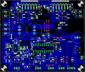
Considering that you seem to have discovered the curved track feature of Eagle 4.11 only in the last 24 hours, did you design the PCB just now? That's one fast design.roadkill said:Here's an LM3886 stereo board, with input buffering opamp, LM1036 based volume/balance/bass/treble controls. Expects well filtered DC (4700uF or more). Comments welcome.
I've decided to give your recommended terminal blocks a try. I went looking for Phoenix connectors, and Visha seems to have some, made by an Indian company, but as per the Phoenix design. The moving part of the vice is the lower part; the upper part stays fixed. As you loosen the screw, the lower half moves down, widening the gap. As you tighten, it rises up and grips the wire. They have them in 0.2" pitch, and in two sizes. One for about 1A or so rating, and another, larger one for 10A rating. This series seems to be better made than the ones I've seen earlier of roughly the same size, and I've bought some. I'll use these for the current amp I'm building, and see how it goes. I'll use the 10A rated ones for power amp supply and speaker outputs, and the smaller ones for preamp supply lines.roadkill said:This is why I'm almost fanatical about using connectors of some form. For high-current stuff (amp power, speakers, etc) I use screw terminals (Phoenix Contact). For signal level, it's usually Relimate connectors. This also makes modding the amp easier (that's what it's all about in the end, right?)
For signal level connections, I found Relimate at Visha. But the movable part of each block (which is female), is crimp-on. Do you have a crimping tool for this?
Visha sells these Relimate connectors with about a foot of unshielded hookup cable crimped to each lead. For audio work, I'll need shielded cable. Will I need to invest in a crimping tool too?
I started this design about two hours before I read your post. I had finished laying out most of the components, so I opened it up with the new Eagle and routed it with curved traces.Considering that you seem to have discovered the curved track feature of Eagle 4.11 only in the last 24 hours, did you design the PCB just now? That's one fast design.
You must be refering to an Indian connector company UNIX, their products are quite decent (moving cage type). Other manufacturers use poor quality plastic, which often melts during soldering. Note: soldering these babies needs a LOT of heat, esp if it's to a plane.I've decided to give your recommended terminal blocks a try. I went looking for Phoenix connectors, and Visha seems to have some, made by an Indian company, but as per the Phoenix design
I've always wanted a crimper, but I currently use a pair of nose pliers. You can also try buying the ones with the unshielded wire, clipping them short and then soldering them to a length of shielded wire. Be sure to use a generous amount of heatshrink tubing of the right dia to transfer stress on the shielded wire to the PVC insulation of the unshielded wire. This is important, else this soldered joint may break. <flame_guard=on>Or if the lengths are short, use them unshielded!<flame_guard=off>.Visha sells these Relimate connectors with about a foot of unshielded hookup cable crimped to each lead. For audio work, I'll need shielded cable. Will I need to invest in a crimping tool too?
One thing I'm considering is to use the cables commonly used to connect CD Rom drive audio outputs to the sound card. This stuff has a connector already fixed to a length of twin shielded wire. You can get them with single shielded wire too (used for transfering digital audio to the soundcard) but these are a little more rare. The tough thing to find is the board-mounting section. Sure, they will mate to a berg stick, but then they wont be polarized. The proper mating section has a plastic shroud which polarizes the connector and locks it in place. A lever mechanism is used to unlock the connector. Good stuff... now I need to find it someplace cheap...
Hi knabsol and gogo, thanks for your interest. Please note, as I have already mentioned, these amps require an external filter cap pair, the ones provided on the board are for local decoupling only. Also, the speaker output terminal block's second terminal is connected to the system star ground, as should be the speaker's ground return.
I have used the same circuit on a different board for a small instrument amp I made for some friends, it works fine. I've also helped another friend build a stereo amp with a pair of these (same board design). I will be using five of them myself for a 5.1 system, which looks like it will never see the light of day... These boards are what I attached a pic of, some posts back. They use the isolated version of the 3886.
Anyway, here are the Eagle board and schematic files. These were created in Eagle 4.03
BTW, knabsol, you can download Eagle from www.cadsoftusa.com and use it to print the boards. You can also use it's CAM processor to generate a gerber. If you want, I can mail you the PDFs/gerbers or post them here.
I have used the same circuit on a different board for a small instrument amp I made for some friends, it works fine. I've also helped another friend build a stereo amp with a pair of these (same board design). I will be using five of them myself for a 5.1 system, which looks like it will never see the light of day...
These boards are what I attached a pic of, some posts back. They use the isolated version of the 3886.Anyway, here are the Eagle board and schematic files. These were created in Eagle 4.03
BTW, knabsol, you can download Eagle from www.cadsoftusa.com and use it to print the boards. You can also use it's CAM processor to generate a gerber. If you want, I can mail you the PDFs/gerbers or post them here.
Attachments
Will remember.roadkill said:You must be refering to an Indian connector company UNIX, their products are quite decent (moving cage type). Other manufacturers use poor quality plastic, which often melts during soldering. Note: soldering these babies needs a LOT of heat, esp if it's to a plane.
This is what I was thinking of too! Should work, shouldn't it?I've always wanted a crimper, but I currently use a pair of nose pliers. You can also try buying the ones with the unshielded wire, clipping them short and then soldering them to a length of shielded wire.
So now I save money on the crimping tool only to blow it on a heat gun. Sigh...Be sure to use a generous amount of heatshrink tubing of the right dia...
Thanks for the pointers.
Tarun
- Status
- This old topic is closed. If you want to reopen this topic, contact a moderator using the "Report Post" button.
- Home
- Amplifiers
- Chip Amps
- Lm3886 Pcb