They do not need to be connected together................ Also the earth ground and the start ground must be connected both using the same screw in the chassis. Some people ground earth ground in one side of the chassis and the start in another place in the chassis. They need to be tied together in the chassis..............
I have found they work BETTER if they are separated, The Safety Earth connects PE direct to Chassis where the Mains cable enters the Chassis.
The MAG connection to Chassis at the MAG location, i.e. near the input and output and amplifier connections.
In addition:
The Safety Earth is a PERMANENT connection. It must not share the bolted connection with other parts that may require periodic dismantling.
I know that it was last month that you asked this.Shorten the Protective Earth (PE) wire and bolt it next to the mains cable entry hole.
This Safety Earth is permanent and should never be dismantled.
Is Green/yellow sleeving available in the USA?
But ONLY use it on the PE wire, no where else.
The NEC code 250.119 on wire color code:
....equipment grounding conductors shall be permitted to be bare,
covered, or insulated. Individually covered or insulated equipment grounding conductors shall have a continuous outer finish that is either green or green with one or more yellow stripes except as permitted in this section.
Supply Problems maybe?
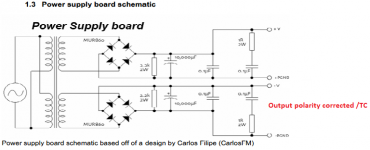
I don't know if someone caught this earlier but I believe that your power supply is wired wrong. The bridge on the lower half (the negative side) will put an inverse polarity across the main power supply filter cap (10K uf) and the voltage polarity going to the amp will also be incorrect. The two cathodes of the bridge should be connected to the common ground and the two anodes should connect to the -V supply. I'm surprised that you haven't blown the amps and or the 10K filter cap if it was wired as shown.
Cheers
Philip
DUH! Facepalm! Yeah... The PG- and V- connections on the supply schematic are reversed. I can't believe that schematic is still floating around.
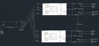
I don't know for sure, but I have a sneaky suspicion that the boards are wired correctly but the schematic is wrong. I suggest double-checking with the corrected schematic below.
~Tom
I don't know for sure, but I have a sneaky suspicion that the boards are wired correctly but the schematic is wrong. I suggest double-checking with the corrected schematic below.
~Tom
Attachments
Good deal. The circuit should work then.
I'm guessing you're using a 3.5 mm headphone jack to RCA cable to connect to your phone. What happens if you plug in both RCAs but leave the 3.5 mm end floating? Still hum?
Do you have a voltmeter? With the input cable disconnected, try measuring the voltage (both DC and AC) between the outer ring ("ground") on the two RCA jacks. I.e. touch the outer ring of one jack with the (+) lead of the voltmeter and the outer ring of the other RCA jack with the (-) lead. There should be no voltage here (neither DC or AC). If you have voltage here, I bet you accidentally swapped the transformer windings between the two boards.
If you're dealing with a ground loop, you should be able to make the amplitude change by moving the wires around. If you bundle all the wires tightly, the amplitude should go down. Likewise if you make the RCA cable shorter (you could emulate that by touching the outer ring of the two RCAs with a piece of wire - after confirming that you don't have voltage between them), the hum amplitude should be lower.
Personally, I think the problem is with the hookup of the power transformer. One thing you can try is to hook the transformer to only one rectifier board and use the output from that board to supply both channels. I don't know if the rectifier board can handle that at max output power (probably not), but for a quick test at a few watt output power (still damn loud), it should be fine.
Yuck. Here in Seattle, we consider 90 ºF (low 30ies ºC) to be very hot. 100 ºF (40 ºC) would be unbearable, "why didn't I get a house with air-conditioning" hot...
~Tom
")
DUH! Facepalm! Yeah... The PG- and V- connections on the supply schematic are reversed. I can't believe that schematic is still floating around.
I don't know for sure, but I have a sneaky suspicion that the boards are wired correctly but the schematic is wrong. I suggest double-checking with the corrected schematic below.
~Tom
I have the boards wired per the markings on the board, PG- etc go to their respective traces. I should, however, make sure the boards are marked correctly. Furthermore, and in response to another post, there are the only wires I have not succesfully twisted, they are only about 1in long the way the boards are mounted together. Would that be worth a try? They are fairly close to the input cables (power supplies leads, inputs, and outputs are all within a couple inches from eachother on the amp boards), and both use pretty crappy wiring. First thing on my list is to check the transformer wiring.
I haven't had much time this week, but I might have some time tomorrow evening or this weekend, and I will get back to you all. Tom, thanks for the optimism.
I have the boards wired per the markings on the board, PG- etc go to their respective traces. I should, however, make sure the boards are marked correctly. Furthermore, and in response to another post, there are the only wires I have not succesfully twisted, they are only about 1in long the way the boards are mounted together. Would that be worth a try? They are fairly close to the input cables (power supplies leads, inputs, and outputs are all within a couple inches from eachother on the amp boards), and both use pretty crappy wiring. First thing on my list is to check the transformer wiring.
Also check to see if the negative side 10,000 uF filter cap is not reverse polarized as was shown in the original power supply schematic. It should be connected as per tomchr revised drawing. In fact it might be a good idea to check if the cap is still functional if it was ever powered with a reverse polarity, also check the bridge, there may be a bad rectifier.
Cheers
Philip
Dug,
you are shown as Canada. May I presume you have adopted the british convention of Grn/Yel for PE?
But, does that apply across the border in the USA. They don't like changing anything from what they adopted two centuries ago.
What we did change 2 centuries ago was our adoption of independence. I have seen a lot of the Green/ Yellow coding of protective ground wires here but I doubt it was issue 2 centuries ago ?
Furthermore, and in response to another post, there are the only wires I have not succesfully twisted, they are only about 1in long the way the boards are mounted together. Would that be worth a try?
Twisting the power supply wires is not likely to resolve the hum issue.
Tom, thanks for the optimism.
You're welcome.
Also check to see if the negative side 10,000 uF filter cap is not reverse polarized as was shown in the original power supply schematic. It should be connected as per tomchr revised drawing.
If the circuit was connected as shown in the schematics attached to Post #1, all supply caps should be fine. But wiring the circuit that way would result in 0 V across the LM3886 and any electrolytic caps on the VEE supply would likely have blown up. I doubt the boards are connected as shown in the schematics.
~Tom
Hi,
You can do a simple test to verified that the PS it is okay.If you read the rails voltage with the meter selected in AC and read the rails voltage. You should read both voltage almost zero volts. High voltage means that the capacitors and diodes are not working like it is suppose.
You can do a simple test to verified that the PS it is okay.If you read the rails voltage with the meter selected in AC and read the rails voltage. You should read both voltage almost zero volts. High voltage means that the capacitors and diodes are not working like it is suppose.
DUH! Facepalm! Yeah... The PG- and V- connections on the supply schematic are reversed. I can't believe that schematic is still floating around.
I don't know for sure, but I have a sneaky suspicion that the boards are wired correctly but the schematic is wrong. I suggest double-checking with the corrected schematic below.
~Tom
Unfortunately, this bad schematic has been floating around for ages
and gets picked up by folks every now and then.
That bad schematic is part of the chipamp.com user guide. It will keep returning until they fix it.
http://chipamp.com/docs/lm3886-manual.pdf
http://chipamp.com/docs/lm3886-manual.pdf
Last edited:
Hi,
You can do a simple test to verified that the PS it is okay.If you read the rails voltage with the meter selected in AC and read the rails voltage. You should read both voltage almost zero volts. High voltage means that the capacitors and diodes are not working like it is suppose.
Now I believe we are getting somewhere guys. I checked wiring today, all is well. Boards are wired up with 0V to AC1bar and AC2bar. 18V is connected to AC1 and AC2. Caps appear to be correct polarity, etc. With amp boards still connected, I measured 27V DC on both boards from V+ to PG+ and from V- to PG-, the same as I originally measured after initially soldering the boards. Interestingly, I also measure 58V AC across the same contacts on BOTH boards. I have the chips and amp boards hooked up, but that shouldn't generate 58V AC should it? I'm somewhat skeptical because its exactly the same voltage on both boards, but does this mean the rectifier is bad? I have enough MUR diodes around to replace all of them, caps is a different story.
Can you draw a schematic of your circuit (combine the pictures in Post #1) that shows how everything is hooked together and where you are measuring the voltages? That'll make it a lot easier to follow what you're doing.
If you keep the negative probe of the DMM on PG+ (or PG-, they should be the same voltage) and touch V+ with the positive probe, you should see +27 V DC. If you touch V- with the positive probe, the DMM should read -27 V DC.
If you perform the same measurement with the DMM set to AC V, it should read a high voltage for a fraction of a second when you touch the positive probe to V+ or V-, but settle to a low value of AC voltage. With decent sized supply caps (say 4700 uF or above) I would expect no more than 50-100 mV AC on the supply rails. If you see more than that, something is wrong.
Your DMM should have a diode test function. Usually, if you connect the positive lead of the DMM to the anode of the diode and the negative lead to the cathode, the DMM will beep once and show the diode voltage drop (0.5~1.0 V depending on the type of diode). If you reverse the connections, the DMM should read infinite, indicating that the diode does not conduct in the reverse bias condition.
~Tom
Can you draw a schematic of your circuit (combine the pictures in Post #1) that shows how everything is hooked together and where you are measuring the voltages? That'll make it a lot easier to follow what you're doing.
If you keep the negative probe of the DMM on PG+ (or PG-, they should be the same voltage) and touch V+ with the positive probe, you should see +27 V DC. If you touch V- with the positive probe, the DMM should read -27 V DC.
If you perform the same measurement with the DMM set to AC V, it should read a high voltage for a fraction of a second when you touch the positive probe to V+ or V-, but settle to a low value of AC voltage. With decent sized supply caps (say 4700 uF or above) I would expect no more than 50-100 mV AC on the supply rails. If you see more than that, something is wrong.
Your DMM should have a diode test function. Usually, if you connect the positive lead of the DMM to the anode of the diode and the negative lead to the cathode, the DMM will beep once and show the diode voltage drop (0.5~1.0 V depending on the type of diode). If you reverse the connections, the DMM should read infinite, indicating that the diode does not conduct in the reverse bias condition.
~Tom
Here is a schematic. The diode test function seems worthless while the diodes are mounted (or they are all bad), because I get voltage through in both directions.
Today, I moved both amps to a single power supply so that I can further simplify things and troubleshoot that way. It still had the same hum. I still had some time and 14 diodes sitting around that Digikey send me erroneously. So, when logic fails, brute force approach, replaced all the diodes on the PS that I had connected to the trafo. Solved the hum issue in 1 speaker, interesting. The second PS is still in the circuit but not receiving AC power from the transformer (V+ PGND+, V-, PGND- between amp and PS are still attached, but the AC leads to the PS are disconnected). Somehow I STILL get 55V AC on the PS rails, even with all new diodes.
I still had 6 diodes left over, so I replaced 6 on the second board that is not getting AC power. No change. I will likely replace the other 2 just to convince myself it is not a diode issue related to overloading them when I had it shorted before.
These are the diodes I am using
Attachments
Hi,
You mentioned that you read 58 volts AC in the rails of the PS. If you read AC in the rails means you capacitors are open or no good. Remember that the diodes conducted in the forward direction. In other word will removed the negative side of the AC sine wave. Means that you will have what we called DC pulsating. It is up to the capacitors to smooth it as closed to a battery DC. You can read DC pulsation with the voltmeter in AC. That was the test I advised to do. Check the capacitors to see if they are good. When you read the 58 volts do you read it with the meters lead connected to PS+ and the PS-.
You mentioned that you read 58 volts AC in the rails of the PS. If you read AC in the rails means you capacitors are open or no good. Remember that the diodes conducted in the forward direction. In other word will removed the negative side of the AC sine wave. Means that you will have what we called DC pulsating. It is up to the capacitors to smooth it as closed to a battery DC. You can read DC pulsation with the voltmeter in AC. That was the test I advised to do. Check the capacitors to see if they are good. When you read the 58 volts do you read it with the meters lead connected to PS+ and the PS-.
https://www.youtube.com/watch?v=_3G8t-cV1d8
Explaining diode testing. You can skip the first six minutes.
Test each diode before placing on PCB.
Explaining diode testing. You can skip the first six minutes.
Test each diode before placing on PCB.
- Status
- This old topic is closed. If you want to reopen this topic, contact a moderator using the "Report Post" button.
- Home
- Amplifiers
- Chip Amps
- LM3886 Oscillation?