The TWO input interconnects are creating a LOOP.
That loop can only be broken by splitting the SOURCE common Ground.
That solution is generally impossible.
Instead you can build mono blocks. These are isolated from each other. That prevents the creation of the input loop.
A third method is to build a dual mono with isolated channels. This needs separate secondary windings to each channel.
This prevents creation of the input loop.
BUT !!!!!! you are required to add a link from Chassis to all exposed conductive parts. This creates a loop with the TWO input interconnects.
A fourth method is to build a stereo with a common ground for the two channels.
The solution here is not to break the loop, that breaks the two wire connection circuit.
Instead you add resistance into parts of the loop such that the interfering voltage drop on the signal wiring becomes low enough to not cause perceivable damage to the wanted signal.
This final method of adding resistance to some parts of the circuit or circuits is a very powerful technique. But you have to work out WHERE to place the added resistance so that you preserve the wanted signal.
There is a paper that describes exactly how to find these inadvertent loops and where to place the added resistances.
It has been linked a few times on this Forum.
I have downloaded it and printed it, but don't have the address. I'll see what I can find.
Last edited:
Here are a few things that you could try:
1. Follow the users guide, it explains how to first connect the PSU board to the transformer, then measure, then connect the amp board, then measure, etc. If you had done this from the start you would not have made such a catastrophic mistake.
2. Best to build two mono amps or a stereo amp. Your two PSU boards connected to a single transformer is a configuration not often seen and it is not explained in the CHIPAMP.COM users guide. If you want to experiment when you have things working that it fine, but for now best to keep to the users guide.
3. Try different sources. A CD PLAYER would be best. You don't know what kind of signals (RF) are coming out of your telephone. My phone even uses the headphones as a radio antenna.
4. Place a stereo potentiometer or resistor network before the inputs of both amps. See the users guide. it will reduce noise from the source.
5. No instructions in the users guide on how to connect two amp boards to a single PSU board. You could try something like this:

Different mains plug of course.
Its important to keep the ground connections short, which in this case should not be a problem. I would recommend twisting supply and returns where possible.
If you want to build two mono amps just follow the users guide.
6. The heatsink seems to small, although it is larger than what is advised in the users guide. If you have the TF type chips, do not insulate the chips from the heatsink, fasten the chips directly to the heatsink. Don't place a plate between the chips and heatsink, it will only reduce the heat transfer.
7. Use the correct coloured leads and insulate all mains connections.
I hope some of this info was helpful.
1. Follow the users guide, it explains how to first connect the PSU board to the transformer, then measure, then connect the amp board, then measure, etc. If you had done this from the start you would not have made such a catastrophic mistake.
2. Best to build two mono amps or a stereo amp. Your two PSU boards connected to a single transformer is a configuration not often seen and it is not explained in the CHIPAMP.COM users guide. If you want to experiment when you have things working that it fine, but for now best to keep to the users guide.
3. Try different sources. A CD PLAYER would be best. You don't know what kind of signals (RF) are coming out of your telephone. My phone even uses the headphones as a radio antenna.
4. Place a stereo potentiometer or resistor network before the inputs of both amps. See the users guide. it will reduce noise from the source.
5. No instructions in the users guide on how to connect two amp boards to a single PSU board. You could try something like this:
Different mains plug of course.
Its important to keep the ground connections short, which in this case should not be a problem. I would recommend twisting supply and returns where possible.
If you want to build two mono amps just follow the users guide.
6. The heatsink seems to small, although it is larger than what is advised in the users guide. If you have the TF type chips, do not insulate the chips from the heatsink, fasten the chips directly to the heatsink. Don't place a plate between the chips and heatsink, it will only reduce the heat transfer.
7. Use the correct coloured leads and insulate all mains connections.
I hope some of this info was helpful.
Attachments
Last edited:
Maybe I'm an idiot but with AC does it matter which line off the mains I switch? One is always available to bite you if you are grounded correct? You're saying move the switch to the other AC terminal?
I'm not familiar with the the US mains wiring and how the A.C relates to ground but I would play it safe and use a two pole switch and switch both conductors
Even where I live where one of the A.C conductors (neutral) is at ground potential and only the other A.C conductor (phase) has voltage with respect to ground, I still use a double poll mains switch and switch both the phase and the neutral, mainly to guard against incorrect house or power cord wiring, however unlikely that may be. That way, I know when it's switched off, its all off
")
Only the safety earth should be permanently connected, it should have its own connection to the chassis
There are 2 options for the leads on R3, one for if Ci is used, one for if it is not. I checked if it is grounded in the configuration, it is.
Good deal. The circuit should work then.
Tried two different cables yesterday and had the same result with both. With only either RCA connected to either channel, I get no hum. The problem arises when I connect the other RCA. No music playing, loud hum, music playing, quieter hum, slower frequency. Sounds similar to 60hz to my untrained ear. it changes pitch when I stop music playing. I have tried yet another source to no avail.
I'm guessing you're using a 3.5 mm headphone jack to RCA cable to connect to your phone. What happens if you plug in both RCAs but leave the 3.5 mm end floating? Still hum?
Do you have a voltmeter? With the input cable disconnected, try measuring the voltage (both DC and AC) between the outer ring ("ground") on the two RCA jacks. I.e. touch the outer ring of one jack with the (+) lead of the voltmeter and the outer ring of the other RCA jack with the (-) lead. There should be no voltage here (neither DC or AC). If you have voltage here, I bet you accidentally swapped the transformer windings between the two boards.
If you're dealing with a ground loop, you should be able to make the amplitude change by moving the wires around. If you bundle all the wires tightly, the amplitude should go down. Likewise if you make the RCA cable shorter (you could emulate that by touching the outer ring of the two RCAs with a piece of wire - after confirming that you don't have voltage between them), the hum amplitude should be lower.
Personally, I think the problem is with the hookup of the power transformer. One thing you can try is to hook the transformer to only one rectifier board and use the output from that board to supply both channels. I don't know if the rectifier board can handle that at max output power (probably not), but for a quick test at a few watt output power (still damn loud), it should be fine.
It doesn't help that I'm doing all this in my garage in AZ, it's probably ~110*F in there all day.
Yuck. Here in Seattle, we consider 90 ºF (low 30ies ºC) to be very hot. 100 ºF (40 ºC) would be unbearable, "why didn't I get a house with air-conditioning" hot...
~Tom
The UK requires the mains switch to be two pole.
This is to ensure when OFF, that swapped Live & Neutral do not leave the equipment "Live".
Yep! +1 for two-pole mains switches.
~Tom
The TWO input interconnects are creating a LOOP.
That loop can only be broken by splitting the SOURCE common Ground.
That solution is generally impossible.
Instead you can build mono blocks. These are isolated from each other. That prevents the creation of the input loop.
A third method is to build a dual mono with isolated channels. This needs separate secondary windings to each channel.
This prevents creation of the input loop.
BUT !!!!!! you are required to add a link from Chassis to all exposed conductive parts. This creates a loop with the TWO input interconnects.
A fourth method is to build a stereo with a common ground for the two channels.
The solution here is not to break the loop, that breaks the two wire connection circuit.
Instead you add resistance into parts of the loop such that the interfering voltage drop on the signal wiring becomes low enough to not cause perceivable damage to the wanted signal.
This final method of adding resistance to some parts of the circuit or circuits is a very powerful technique. But you have to work out WHERE to place the added resistance so that you preserve the wanted signal.
There is a paper that describes exactly how to find these inadvertent loops and where to place the added resistances.
It has been linked a few times on this Forum.
I have downloaded it and printed it, but don't have the address. I'll see what I can find.
Here are a few things that you could try:
1. Follow the users guide, it explains how to first connect the PSU board to the transformer, then measure, then connect the amp board, then measure, etc. If you had done this from the start you would not have made such a catastrophic mistake.
2. Best to build two mono amps or a stereo amp. Your two PSU boards connected to a single transformer is a configuration not often seen and it is not explained in the CHIPAMP.COM users guide. If you want to experiment when you have things working that it fine, but for now best to keep to the users guide.
3. Try different sources. A CD PLAYER would be best. You don't know what kind of signals (RF) are coming out of your telephone. My phone even uses the headphones as a radio antenna.
4. Place a stereo potentiometer or resistor network before the inputs of both amps. See the users guide. it will reduce noise from the source.
5. No instructions in the users guide on how to connect two amp boards to a single PSU board. You could try something like this:
View attachment 421707
Different mains plug of course.
Its important to keep the ground connections short, which in this case should not be a problem. I would recommend twisting supply and returns where possible.
If you want to build two mono amps just follow the users guide.
6. The heatsink seems to small, although it is larger than what is advised in the users guide. If you have the TF type chips, do not insulate the chips from the heatsink, fasten the chips directly to the heatsink. Don't place a plate between the chips and heatsink, it will only reduce the heat transfer.
7. Use the correct coloured leads and insulate all mains connections.
I hope some of this info was helpful.
I'm building this amp off of the BOM of someone else. I don't know if DIYAudio allows to post external links, but it's a small desktop amp over at PE. I didn't realize this was such an uncommon setup, I will PM the original builder and see how he/she wired things. Also, yes, I am stupid for not using a bulb tester the first time around. I use one now. I actually did test voltages as in the manual, but had things wired differently.
Good deal. The circuit should work then.
I'm guessing you're using a 3.5 mm headphone jack to RCA cable to connect to your phone. What happens if you plug in both RCAs but leave the 3.5 mm end floating? Still hum?
no hum.
Will check.Do you have a voltmeter? With the input cable disconnected, try measuring the voltage (both DC and AC) between the outer ring ("ground") on the two RCA jacks. I.e. touch the outer ring of one jack with the (+) lead of the voltmeter and the outer ring of the other RCA jack with the (-) lead. There should be no voltage here (neither DC or AC). If you have voltage here, I bet you accidentally swapped the transformer windings between the two boards.
Amplitude does not change. I've shuffled around the amps, twisted the wired, moved them around while it's humming...nothing. Always the same.If you're dealing with a ground loop, you should be able to make the amplitude change by moving the wires around. If you bundle all the wires tightly, the amplitude should go down. Likewise if you make the RCA cable shorter (you could emulate that by touching the outer ring of the two RCAs with a piece of wire - after confirming that you don't have voltage between them), the hum amplitude should be lower.
Personally, I think the problem is with the hookup of the power transformer. One thing you can try is to hook the transformer to only one rectifier board and use the output from that board to supply both channels. I don't know if the rectifier board can handle that at max output power (probably not), but for a quick test at a few watt output power (still damn loud), it should be fine.
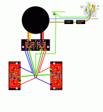
I'll check one last time. Right now, I have each secondary paralleled to both amps. Here is a pretty good picture of how they are wired. AC1 and AC2 are in parallel with the opposing PS board.
Yep! +1 for two-pole mains switches.
~Tom
Well, I hate the switch I have because of the way it mounts so I will purchase a 2 pole.
Last edited:
Good deal. The circuit should work then.
Do you have a voltmeter? With the input cable disconnected, try measuring the voltage (both DC and AC) between the outer ring ("ground") on the two RCA jacks. I.e. touch the outer ring of one jack with the (+) lead of the voltmeter and the outer ring of the other RCA jack with the (-) lead. There should be no voltage here (neither DC or AC). If you have voltage here, I bet you accidentally swapped the transformer windings between the two boards.
Personally, I think the problem is with the hookup of the power transformer. One thing you can try is to hook the transformer to only one rectifier board and use the output from that board to supply both channels. I don't know if the rectifier board can handle that at max output power (probably not), but for a quick test at a few watt output power (still damn loud), it should be fine.
~Tom
~14mv DC, no AC with RCA hooked up to inputs but not plugged into source. ~5mvDC, no AC when hooked up to source. Does that tell you anything?
I started looking at my wiring to make sure it matched the diagram I posted but I chickened out, too hot.
~14mv DC, no AC with RCA hooked up to inputs but not plugged into source. ~5mvDC, no AC when hooked up to source. Does that tell you anything?
I would have expected 0.0 mV DC. The two signal grounds should connect to the board ground. Right channel signal ground (return) goes to right channel board ground. Ditto for the left channel. The board grounds for the two channels then go to the chassis ground point. The DC voltage between the two should be 0.
It's possible that your DMM has a small offset. Do you get 0 V when you touch the probes together?
I started looking at my wiring to make sure it matched the diagram I posted but I chickened out, too hot.
No worries.
If you don't want to use two transformers, I think your best bet is to use only one supply. So one transformer, one supply board feeding two amp boards.
This is a bit of a long shot, but suppose the diodes are slightly different in characteristics (they are - production tolerances). This would cause the diode bridge in one amp to shut off sightly before the other. As the ground connections are shared between the two amps, would that set up a wonky current flow that's basically a 60 Hz impulse train? I'd need to draw it out to work it out, and as I said, it's a bit of a long shot...
I've built a circuit exactly as the one you have. Even with a crappy layout and long leads going to a lab supply shared between the two channels, it worked just fine. No hum or other nastiness. This leads me to believe there's a flaw in your system. I'm sure we can figure this one out.
Ugh, this thread hurts to read. As such I haven’t read all of it, so I’ll apologize if you’ve already tried this, but have you put 470 pF caps across the R2 (22K) locations?
This thread deals with mains hum, not instability. Adding 470 pF (which is way too much anyway) won't do anything for mains hum.
~Tom
No !!!!Then the input should be fed first to a two-pole ganged breaker.
First is the mains fuse in the Live feed.
This thread deals with mains hum, not instability. Adding 470 pF (which is way too much anyway) won't do anything for mains hum.
~Tom
Okay, I’ll take your word for it. I only mentioned the caps reading from his initial post description. Parts getting hot fast can be indicative of an oscillation producing cross-conduction in the output stage. When that occurs PSRR can go to hell and hum occur. It also increases power demand, so current through the bridge(s) goes up (hence more radiated noise) as well as increased rail ripple.
Why do you say 470 pF is way too much? It's a good starting point, it's value is layout dependent with many amps needing less, and a few needing more. With the input potentiometer set at its maximum impedance the pole is at 62 KHz.
Why do you say 470 pF is way too much? It's a good starting point, it's value is layout dependent with many amps needing less, and a few needing more.
Sorry. You said across R2. I read Rf... R2 goes from the non-inverting input to GND. You can put 470 pF across there. That might be a tad much, I usually aim for fc = 200 kHz, but each to his own. Adding a cap across R2 will also reduce RF injection into the circuit.
You're right about the quasi-oscillations of the output stage. That can happen when the amp is driven into clipping if the non-inverting input is loaded by a high impedance.
I don't think the OP is dealing with oscillations. That's just one of the many scapegoats that people use when they're having trouble with their chipamp circuits...
The title of the thread is misleading. I bet he's dealing with a wiring issue or a ground loop. My money is on the wiring issue.~Tom
While we often touch on this in other threads, in the above drawings, the AC power line ground connection to the chassis is not part of the Main Audio Ground connection to the chassis. The AC power line ground connection to the chassis should be near the power line inlet. The MAG connection to the chassis should be near the Input/Output jacks.
" Originally Posted by DUG View Post
Then the input should be fed first to a two-pole ganged breaker.
"
Breaker.
I agree fuse before switch but breaker is both.
Then the input should be fed first to a two-pole ganged breaker.
"
No !!!!
First is the mains fuse in the Live feed.
Breaker.
I agree fuse before switch but breaker is both.
Hi,
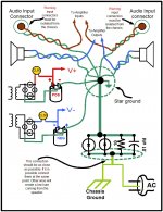
I looked at you pictures and noticed that you do not have the PS, Ac and the input wires twisted. Specially the input wires. You should use twisted wires for the input. Also do a test. This is a only a test. Removed the amplifier start ground from the chassis and see if the hum goes a way. Also the earth ground and the start ground must be connected both using the same screw in the chassis. Some people ground earth ground in one side of the chassis and the start in another place in the chassis. They need to be tied together in the chassis.
Also attached it is a star ground drawing that I used successfully in my 3 LM3886 built. You can use it as a reference.
Attachments
The CL-60 should be on the primary, not the secondary. It should also be bypassed by a relay after it's done limiting the in-rush current. The idle current of the amp is not enough to heat up the CL-60.
Moving the star ground away from the LM3886 is not a recipe for success. I have a bunch of data in This Thread. The entire thread is worth reading.
~Tom
Moving the star ground away from the LM3886 is not a recipe for success. I have a bunch of data in This Thread. The entire thread is worth reading.
~Tom
Breaker?" Originally Posted by DUG View Post
Then the input should be fed first to a two-pole ganged breaker.
"
Breaker.
I agree fuse before switch but breaker is both.
Is that an Equipment version of the MCB (miniature circuit breaker) usually fitted at the distribution board?
- Status
- This old topic is closed. If you want to reopen this topic, contact a moderator using the "Report Post" button.
- Home
- Amplifiers
- Chip Amps
- LM3886 Oscillation?