<< Currently, you're making a perfect wheel square. >>
Best you've got for a logical argument? I weep.
That's the only way you found to avoid addressing the rest of the post ? And post 15 entirely ?
Last edited:
<<<BUT IMPORTANTLY, I have a growing suspicion that I'm overdoing the whole thing. As long as the audio signal is kept away from the power supply lines, do other things much matter? Maybe not much, and two reasons for thinking this.>>>
Should the priority not be for the capacitors to supply current to the opamps?
There are three types of currents that need to be considered. 1. Charging currents from the transformer(s). 2. Charging and supply currents from cap to cap. 3. Supply currents from caps to opamps.
If you do the simulations you can see these complex currents interacting and how the inductance of the ground layout badly influences these currents. What is the point of a bypass capacitor that is not working properly or even oscillating because of the high series inductance of the ground?
Last edited:
.
When in the course of human events...I decided some sort of explanation was necessary.
First of all, efforts to "prove to the guy how wrong he is" are wasted on me, so save your venom. I'm interested in what's right, not what's wrong.
Otherwise, I see seven blind men trying to figure out an elephant. Much discussion of parts, no focus on the whole. Or even ignoring entirely the circuit I posted, in which case what are you discussing at all?
For example, "The CT [center tap - ed.] connects to that reservoir ground, NOT to the 'tee" of the audio ground." But my circuit has neither reservoir ground nor audio ground, so what's the connection, if any? If there is one the writer doesn't point it out, which makes the critique--to call it that--meaningless.
But more importantly, at different times Mr. Self (since he's the one quoted above) presents different versions of basically the same grounding scheme. These versions are, as has been said, open to interpretation, which is a less than ideal situation that I hope to correct.
My circuit does reconcile these different version into one--I hope--and considers other methods by other sources as well. But various commentators quoting various sources make no such effort that I can see.
So what we wind up with is the blind men deciding there's no such thing as an elephant and going their way. Perhaps leaving the elephant somewhat bemused. All of which is fine with me, but...
...I remain interested--eager--to receive valid corrections. But you have to remember that the average 10 year-old is a lot smarter than me.
.
Last edited:
I've had a read through tomchr's guide, specifically the grounding and decoupling section, with a view to tightening up the board layout a bit.

I've shortened the feedback path, got rid of the full-board ground plane and moved the signal grounds to after the speaker grounds
I still need to add two extra decoupling caps and the output zobel network.
Someone mentioned no mute circuit. My amplifier doesn't need a mute. Do I still need to connect anything to the pin?
I'll still be connecting the ground from the preamp to both boards, which will cause a ground loop, but it shouldn't matter as long as the signal grounds are as close as possible to the feedback and speaker grounds, right?
For whoever said I should use a double sided board - unfortunately I do not have the skills to etch this.
From data sheet:
"RM Mute resistance set up to allow 0.5 mA to be drawn from pin 8 to turn the muting function off."
I believe the chips GND is the return for that signal, so make these two pins function together...
Oh. Derp. I read that as 'on'.

http://www.diyaudio.com/forums/chip-amps/79303-chip-amp-photo-gallery-280.html#post4107696
Here is a nice build yours should resemble its neatness.
Check out these kits, they will demonstrate PCB and ground layouts. audiosector.com, chipamp.com and http://www.diyaudio.com/forums/vendors-bazaar/263866-ljm-new-small-toys-gc-lm3886.html#post4100069
Here is a nice build yours should resemble its neatness.
Check out these kits, they will demonstrate PCB and ground layouts. audiosector.com, chipamp.com and http://www.diyaudio.com/forums/vendors-bazaar/263866-ljm-new-small-toys-gc-lm3886.html#post4100069
Sounds like he is confirming he will just ignore us..
When in the course of human events...I decided some sort of explanation was necessary.
First of all, efforts to "prove to the guy how wrong he is" are wasted on me, so save your venom. I'm interested in what's right, not what's wrong.
Otherwise, I see seven blind men trying to figure out an elephant. Much discussion of parts, no focus on the whole. Or even ignoring entirely the circuit I posted, in which case what are you discussing at all?
For example, "The CT [center tap - ed.] connects to that reservoir ground, NOT to the 'tee" of the audio ground." But my circuit has neither reservoir ground nor audio ground, so what's the connection, if any? If there is one the writer doesn't point it out, which makes the critique--to call it that--meaningless.
But more importantly, at different times Mr. Self (since he's the one quoted above) presents different versions of basically the same grounding scheme. These versions are, as has been said, open to interpretation, which is a less than ideal situation that I hope to correct.
My circuit does reconcile these different version into one--I hope--and considers other methods by other sources as well. But various commentators quoting various sources make no such effort that I can see.
So what we wind up with is the blind men deciding there's no such thing as an elephant and going their way. Perhaps leaving the elephant somewhat bemused. All of which is fine with me, but...
...I remain interested--eager--to receive valid corrections. But you have to remember that the average 10 year-old is a lot smarter than me.
.
As a result he will probably keep telling/showing lots of Members how to do it all wrong.
Sounds like he is confirming he will just ignore us.
As a result he will probably keep telling/showing lots of Members how to do it all wrong.
Indeed. To avoid further polluting the thread, I answered here: http://www.diyaudio.com/forums/analog-line-level/265232-comment-grounding-scheme-2.html#post4141569
Sounds like he is confirming he will just ignore us.
No AndrewT, I'm not ignoring any "us." Just you.
By the way, did you ever hear back from the engineers at SG? I ask because I'm sure they were interested in your critique of their circuit, and I wonder if they changed it to meet your specifications? http://www.diyaudio.com/forums/chip-amps/259494-tda2030-amp-issue-help.html
.
.
First a word of respect for 00940. This because he's the only human being on the face of the earth to actually comment on the circuit that's supposed to be under discussion! This as opposed to pontificating about some pet theory that has nothing to do with the subject at hand. And not only does he stick to the subject...he posts schematics!
In this case I refer to the schematic in post #15, posted again below. Unfortunately, depending on who you're listening to this week, it doesn't quite come up to the mark.
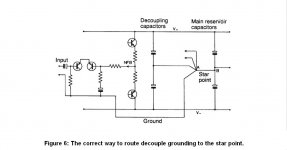
Since we're making free with Douglas Self's schematics I'll continue in that vein. His is posted first below. You know it, you've seen it before. The second circuit is 00940's.
Notice the small but critical difference. Mr. Self emphatically does not make any direct connections to the power supply capacitors. Instead he makes connections via what he calls a "short spur," which is simply a short jumper wire or pc board trace.
Is this jumper, or spur, really so important? Well, Mr. Self says it is, making his case fully in his "Self on Audio," the section entitled "Distortion 5: supply ground loops," page 272.
He makes the same case again in his "Audio Amplifier Design Handbook," related to the schematic in post #12 in this thread.
The same case is presented also in the Texas International publication on grounding that I don't reference again because everybody here knows the one I mean. Yes you do.
All of which seems to be simply (conveniently?) ignored by some. But speaking only for myself, I find all this acknowledged (by me, at least) expertise compelling.
Still, of course others might differ, preferring their own theories, pet or otherwise. And if some do differ then therein I delight, and want to hear all about it. When have I claimed that my circuit is "right"? Never is when. Instead I beg for correction.
But declaiming is not the same as explaining. If you want to make impassioned speeches about your own theories, go right ahead, when have I said no? But if you don't show how your theory relates to the circuit I posted, then...why?
.
First a word of respect for 00940. This because he's the only human being on the face of the earth to actually comment on the circuit that's supposed to be under discussion! This as opposed to pontificating about some pet theory that has nothing to do with the subject at hand. And not only does he stick to the subject...he posts schematics!
In this case I refer to the schematic in post #15, posted again below. Unfortunately, depending on who you're listening to this week, it doesn't quite come up to the mark.
Since we're making free with Douglas Self's schematics I'll continue in that vein. His is posted first below. You know it, you've seen it before. The second circuit is 00940's.
Notice the small but critical difference. Mr. Self emphatically does not make any direct connections to the power supply capacitors. Instead he makes connections via what he calls a "short spur," which is simply a short jumper wire or pc board trace.
Is this jumper, or spur, really so important? Well, Mr. Self says it is, making his case fully in his "Self on Audio," the section entitled "Distortion 5: supply ground loops," page 272.
He makes the same case again in his "Audio Amplifier Design Handbook," related to the schematic in post #12 in this thread.
The same case is presented also in the Texas International publication on grounding that I don't reference again because everybody here knows the one I mean. Yes you do.
All of which seems to be simply (conveniently?) ignored by some. But speaking only for myself, I find all this acknowledged (by me, at least) expertise compelling.
Still, of course others might differ, preferring their own theories, pet or otherwise. And if some do differ then therein I delight, and want to hear all about it. When have I claimed that my circuit is "right"? Never is when. Instead I beg for correction.
But declaiming is not the same as explaining. If you want to make impassioned speeches about your own theories, go right ahead, when have I said no? But if you don't show how your theory relates to the circuit I posted, then...why?
.
Attachments
Indeed. To avoid further polluting the thread, I answered here: http://www.diyaudio.com/forums/analog-line-level/265232-comment-grounding-scheme-2.html#post4141569
It's this one that brought me out of retirement (on this thread) to post these replies. I am, in a certain sense, awestruck. Quoting from the linked comment:
<< The top setup is what you are proposing. >>
No, it's not what I'm proposing. It bears no resemblance. It's an entirely different circuit that apparently you've made up out of thin air.
And having made up this different circuit, you insist it's the same as my circuit, although it obviously is not. You then prove your new circuit doesn't work.
And having proven that your new and different circuit doesn't work, you then announce that therefore my circuit doesn't work--although the two are not similar in any way.
And while all this is going on you mention that oh by the way, there are some extra components in there that I added to prove my own circuit doesn't work, and they also prove your unrelated circuit doesn't work, so just pay no attention to those components behind the curtain.
I remain as before: awestruck.
.
Last edited:
Don't stop. Rant and rave some more please. I just love it, can't get enough.
I am compiling a book of your quotes and you have just given me enough to start a new chapter.
Hmmm? Question? What question?
.
.
I probably shouldn't...what the heck, I am but flesh.
No kidding, 00940, you have my respect. You're the only guy around here with enough nerve to put a schematic where his mouth is.
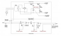
Even so...well...I'm posting the series of 3 schematics you see below.
The first is yours. Actually mine that you modified.
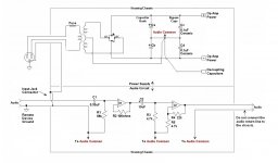
The second is still yours, but I've moved the connecting point for the capacitors and other connections. No other changes.
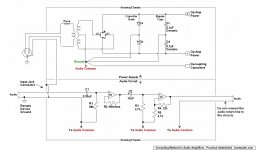
The third is my original.
Right, with the connecting point moved to Mr. Self's "short spur" point you've simply redrawn my schematic.
Of course the whole thing depends on whether you believe in short spurs. Anyway I drew mine as I did hoping for clarity, but I wouldn't argue.
.
I probably shouldn't...what the heck, I am but flesh.
No kidding, 00940, you have my respect. You're the only guy around here with enough nerve to put a schematic where his mouth is.
Even so...well...I'm posting the series of 3 schematics you see below.
The first is yours. Actually mine that you modified.
The second is still yours, but I've moved the connecting point for the capacitors and other connections. No other changes.
The third is my original.
Right, with the connecting point moved to Mr. Self's "short spur" point you've simply redrawn my schematic.
Of course the whole thing depends on whether you believe in short spurs. Anyway I drew mine as I did hoping for clarity, but I wouldn't argue.
.
Attachments

Last edited:
- Status
- This old topic is closed. If you want to reopen this topic, contact a moderator using the "Report Post" button.
- Home
- Amplifiers
- Chip Amps
- LM3886 grounding - Am I doing it right?