Hi,
I am just trying to figure out the best way to wire the grounds on my LM3886 chipamp.
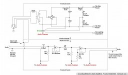
The boards will be of my own design - I have separated the power/speaker ground and the signal/feedback ground as per the layout:

This amp will also have a phono preamp and an active equaliser, powered by a seperate +15/0/-15 supply.
I am just wondering the best way to arrange the grounds as I know it's an important consideration with these chipamps. I've put a (very bad) paint diagram below of what I'm planning to do. Is this right? What's the best way to go about grounding this arrangement?

Cheers
I am just trying to figure out the best way to wire the grounds on my LM3886 chipamp.
The boards will be of my own design - I have separated the power/speaker ground and the signal/feedback ground as per the layout:
This amp will also have a phono preamp and an active equaliser, powered by a seperate +15/0/-15 supply.
I am just wondering the best way to arrange the grounds as I know it's an important consideration with these chipamps. I've put a (very bad) paint diagram below of what I'm planning to do. Is this right? What's the best way to go about grounding this arrangement?
Cheers
I am just trying to figure out the best way to wire the grounds on my LM3886 chipamp.
I would encourage you to use a two layer pcb with a solid ground plane.
The existing plane with traces cutting it up is not very effective.
.
Anything can be made complicated, but remember that the main idea is just to keep the audio signal separated from the power supply. Half the battle right there.
As a reminder, you can build with printed circuit boards and still use jumper wires. Sometimes makes things easier.
Below I'm posting my understanding of "the right way to do it." Which I put in quotes because there is no such thing, everybody has his own pet theories. But possibly of interest.
.
Attachments
.
Thanks for the kind words, Richidoo, but don't be hasty. The subject of grounding has been known to start fistfights around here, there are opposing theories.
.
http://www.diyaudio.com/forums/members/richidoo.html
Thanks for the kind words, Richidoo, but don't be hasty. The subject of grounding has been known to start fistfights around here, there are opposing theories.
.
http://www.diyaudio.com/forums/members/richidoo.html
If you don't have the experience or desire to design something better, it may well be easer and cheaper to purchase a PCB/kit.
If you do want to design a PCB there is a good layout guide in the datasheet.
A few problems that I can see are:
No mute circuit.
C4 GND connection should be close to C1/C2/C3 GND.
Feedback loop (R1) can be smaller.
The input layout and input GND to power GND needs to be redesigned.
Speaker GND could be moved to power GND.
Are you convinced that you do not need any of the optional parts?
You may want to read through: Taming the LM3886 Chip Amplifier
I think you'd get quite a bit out of it.
~Tom
I think you'd get quite a bit out of it.
~Tom
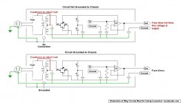
I will not ground the earth.
Please reconsider. For one thing, chassis grounding is required by law in pretty much all jurisdictions.
For another, the danger of having an ungrounded system is real. The posted illustration is intended to show that under some circumstances, any of various faults can result in line voltage being applied to what should be the safe, low-voltage side of the system. The consequences could be fatal.
Unlikely, true. But "unlikely" seems like poor odds when you're betting your life.
.
Attachments
.Below I'm posting my understanding of "the right way to do it." Which I put in quotes because there is no such thing, everybody has his own pet theories. But possibly of interest.
.
It's still the wrong way to do it.
See the difference between your way and D. Self's proposition below (one you quoted yourself actually). And especially what Self means by "0v connection to CT only". If a physical implementation makes things clearer, go to Fig.2 here: Power Supply Wiring Guidelines
Attachments
i never understood that.
i think it is possible that all the soultionjs can be equaly good, and in special cases only 1 of them.
I agree. Many, many chip amps have been bolted together by guys who don't know one end of a soldering iron from the other (tip: one end is hotter).
However, consider an extreme case. A 0.002 volt electret microphone signal being mixed into 15 volts from the power supply. Distortion of the audio (both, actually) seems almost inevitable, and this "extreme case" is actually everyday. Moral: keep the audio away from the power supply.
But of course everything inescapably comes together at ground. So what to do about that--if anything?
I have an ongoing project to distill the grounding advice of every guru known to man into one comprehensible circuit. "Guru" being defined as anybody who wrote a book or published a recognized paper. "Recognized" defined as...well...something somebody thought was worth publishing, or anyway the guy preferably has an engineer degree, although that's not mandatory. Or if the guy just presents a logical argument, that works too.
The problem is that gurus don't always speak human, sometimes their advice is arcane to the point of mystery. My project is an attempt to solve that problem, to make their advice real-world usable.
The present result is the circuit in post #3. I don't represent this as a final authority, or any authority at all. I only offer it for what it is: a distillation of grounding methods known to me into a circuit that I hope is understandable and usable.
In this ongoing project, emphasis on the word "ongoing." At the moment the project has hit a wall, post #3 is a final-ish result. But I greatly hope for further development when/as/if I discover additional facts.
Emphasis on the word "facts." A lot of people have opinions that they consider to be facts, but if they can't show the math, or present a logical argument, then their opinions don't make it into the facts column.
What's a "logical argument"? Among mechanics it's said that if you can't explain what you do to a ten year-old, then you don't really know what you're doing. That's my criterion, take it for what it's worth to you.
BUT IMPORTANTLY, I have a growing suspicion that I'm overdoing the whole thing. As long as the audio signal is kept away from the power supply lines, do other things much matter? Maybe not much, and two reasons for thinking this.
First, a great deal of what we read today is concerned with high speed digital circuits. These operate in the mega- and gigahertz region, little to do with audio.
Second, remember that guy trying to figure out the mysteries of a soldering iron? Well, he banged the thing together somehow, and he wound up with 20 clean watts, so wuz dealie? After all, the whole point of chip amps is that they're supposed to be simple.
.
Last edited:
.
<< It's still the wrong way to do it...See the difference between your way and D. Self's proposition below (one you quoted yourself actually) >>
It's not "my way," as I keep explaining. Does anybody actually read these posts, or do they just look at the pictures?
More directly to your comment, thanks for posting. I'm well familiar with Mr. Elliot's work, as well as Mr. Self's.
But as for seeing the difference you speak of, no I don't. Which is the reason I didn't include any such difference in my circuit to begin with.
If you'd care to actually point out and explain the difference you refer to, as opposed to just saying there is one, my attention will be riveted.
.
Last edited:
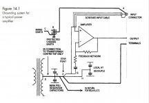
What both Self and Elliot take into account is that the low impedance 0V point of your power supply (from where current is actually sourced) is not the CT of the transformer but the terminals of the main reservoir capacitors. If you put the audio ground in between the CT and the 0V terminals of the main caps, you modulate it with charging currents.
That's what Self means by "0V connection to transformer CT only". If you have a look to Elliot's figure, you'll see the CT connected to one end of the groundplane he uses to link the 0V terminals of the caps and the audio ground taken at the other end. That's intentional, just as, in Self's picture, he has the CT link coming from one side and audio ground from the other.
Your scheme should at least be changed to the one attached. It would help to know exactly what you understand by "bypass" and "decoupling" caps to further refine. Just applying Self's proposition works in most cases so I don't see much the point of reinventing the wheel though.
Attachments
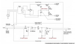
What D. Self and others do not explained if there should be a local bypass ground per channel or per opamp or a single bypass ground for all the opamps combined, they always only draw one opamp or channel. This leaves room for interpretation.
I could not find an example of a D. Self design that uses this bypass layout. The TI datasheets also do not promote a separate bypass ground layout.
I could not find an example of a D. Self design that uses this bypass layout. The TI datasheets also do not promote a separate bypass ground layout.
Sure..
If people are going to edit my schematics I wish they'd remove the reference to bentsnake.com. I disclaim all edited versions.
Currently, you're making a perfect wheel square.The point of my project is exactly to re-invent the wheel. Or rather, to make an imperfect wheel a bit closer to round.
No, you didn't. Please re-read the section in Self's book. The key sentence is "Charging currents for the PSU reservoir capacitors must be kept out of allIn the present case the reference is Douglas Self's "Audio Amplifier Design Handbook," the section entitled "Amplifier Grounding." Mr. Self's comments in the text enlarge upon and explain the circuits shown, I've taken his comments into account in my circuit (I hope).
other grounds." Consider also what Self says about "reservoir ground" in the section about "power amplifier pcb details", a few pages above. The CT connects to that reservoir ground, NOT to the "tee" of the audio ground.
You cannot keep them separate. At one point, you need a common reference and it needs to be clean. Your "compilation scheme" puts it at the worse possible place, a place none of your sources would endorse.Although as before, as long as audio is kept separate from power I'm not certain else is critical.
PS: It might help to remember that current flows out of ground, not into it. Negative to positive, y'know.
I'd be really curious to know how it might help.
edit: btw, the core of my disagreement with your layout (it cannot be said a compilation of good practices) has already been stated by Mark, Andrewt and DF96 in the post 2, 4 and 5 of this thread and restated by Mark in the post 7. Your grounding scheme would be ok if the wire going from your common ground to the center of the main caps has zero resistance and zero inductance. The only way to approach that is to move the common ground to the 0V terminals of the caps. And since a practical implementation of a single point is difficult in real life, Self describes how to approximate it best.
Last edited:
.
If people are going to edit my schematics I wish they'd remove the reference to bentsnake.com. I disclaim all edited versions.
The point of my project is exactly to re-invent the wheel. Or rather, to make an imperfect wheel a bit closer to round.
One more time now--and the last time in this thread--my project is a distillation, a compendium, a compilation.
As such it's really quite a delicate balance. The simplicity of the circuit should be a clue: everything affects everything. No single change is likely to be meaningful or an improvement. The entire circuit, simple though it appears, must be considered.
Although as before, as long as audio is kept separate from power I'm not certain else is critical. To explain that just a bit, Self and others are working at extremely low levels of distortion where a very few decibels become meaningful. Unless your speakers cost $3,000 each I'm not sure of real-world benefits.
In a sidebar, so-called "ground lift" or "loop breaker" arrangements are illegal in all jurisdictions that I know of, and in my opinion are poor substitutes for finding and fixing the real problem--which is probably a loose connection or bad solder joint somewhere.
PS: It might help to remember that current flows from negative to positive. Why somebody came up with the notion of "positive current" I can't fathom.
.
- Status
- This old topic is closed. If you want to reopen this topic, contact a moderator using the "Report Post" button.
- Home
- Amplifiers
- Chip Amps
- LM3886 grounding - Am I doing it right?