I am challenging you to support your assertion with data. You seem to be deflecting by telling me to do it. Is your test equipment broken as well?You are welcome to take your own measurements...
")
Give me some numbers. What is the parasitic L of a 10mF cap and what is it for a 317?
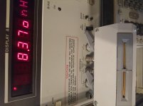
The attached impedance plot is for a Panasonic 10,000uF 50V capacitor as measured on a Hewlett Packard Network Analyzer. The self resonant frequency is 11kHz, ESR at resonance is 0.017 Ohm, and parasitic inductance is about 10nH. The impedance minimum is rather broad, indicating low Q.
Attachments
Give me some numbers. What is the parasitic L of a 10mF cap and what is it for a 317?
I put up an impedance chart of the LM317 a few pages back. You should be able to derive "L" therefrom.
LT1084 is said to be a "Low Dropout Regulator" -- as such the output capacitor will have a significant effect upon loop stability.
I have never seen any product or a competent engineer use giant electro's after a 3T regulator esp. on a non-dynamic load, so the assertion is all yours. IMO Any engineer who did this on his design would have a lot of splainin' to do.I am challenging you to support your assertion with data. You seem to be deflecting by telling me to do it. Is your test equipment broken as well?
BTW You could research PS capacitors through Powercon SMPS papers , theyve pushed the industry the most. Re 4 terminal packages, low ESR etc. but the trend for last 50 years is using more active circuits /neg. feedback instead of brute force passives.
Last edited:
11 KHz seĺf resonance and 10 mF gives 0.209 uH inductance.
ooohps, calculator error: 21.2e-9
I took resonance from the plot at 0 degrees phase. The simple C-ESR-L model for the capacitor is not exact and other means of estimating resonance will yield about 16kHz instead of 11kHz.
I estimated the inductance from the impedance value on the plot at 10MHz.
The resonance calculator at Resonant Frequency Calculator is convenient to use.
For the LM317 the plots published in the article "Understanding and Reducing Noise Voltage on 3-Terminal Voltage Regulators" by Erroll H. Dietz shows a wide variance in the effective inductance depending on operating conditions. The article originally appeared in an old issue of Electronic Design magazine and was reprinted in Pease's book "Troubleshooting Analog Circuits".
For the LM317 the plots published in the article "Understanding and Reducing Noise Voltage on 3-Terminal Voltage Regulators" by Erroll H. Dietz shows a wide variance in the effective inductance depending on operating conditions. The article originally appeared in an old issue of Electronic Design magazine and was reprinted in Pease's book "Troubleshooting Analog Circuits".
The Dietz article was the one that Texas Instruments responded to -- claiming that "transient load response" was adversely affected when the ADJ pin was bypassed.
There is a picture of Bob Pease's desk in the aforementioned book!
Ok. Yes the 317 equivalent L can be derived form the datasheet impedance graphs. It definitely depends on output current. It also depends on frequency. I'm not sure if it depends much on output voltage. Based only on the 500mA graph I'd guestimate it anywhere from 160nH to 3000nH depending on f and how big Cadj is. Very approximately.
I estimated a typical 10000uF 16V cap, based on physical size, to be very roughly 40nH. It depends a lot on the particular cap and so Gerhard's 21nH seems realistic.
So my pedantic point and laboring thereof is in reaction to the notion that a 317 is better at medium and high frequencies than a "huge" cap. I think the opposite (assume appropriate damping is applied in either case).
Edit: Sorry, I overlooked Bill_P's finding of 10nH for a 10mF cap. So I have overestimated.
I estimated a typical 10000uF 16V cap, based on physical size, to be very roughly 40nH. It depends a lot on the particular cap and so Gerhard's 21nH seems realistic.
So my pedantic point and laboring thereof
is in reaction to the notion that a 317 is better at medium and high frequencies than a "huge" cap. I think the opposite (assume appropriate damping is applied in either case).Edit: Sorry, I overlooked Bill_P's finding of 10nH for a 10mF cap. So I have overestimated.
Last edited:
I put up an impedance chart of the LM317 a few pages back. You should be able to derive "L" therefrom.
LT1084 is said to be a "Low Dropout Regulator" -- as such the output capacitor will have a significant effect upon loop stability.
I also thought that. My best set of graphs were with LD1084 ( LM317 as good when dropped into that circuit ). To remind you the LM317 and PNP pass transistor with low Vce ( 0.1V at a guess ) shows more problems. That's in many data sheets and often a 2N2955.
The magic seems to be the 0R33. I noticed the train controller had no problems with the silly 90 000uF. I have to guess it uses something like LM317 as getting inside seems impossible. It was actually much more stable, or so it looked.
Lets be clear. It is hard for me to believe this also. However I've tested it so many times now. The debate should be is the 0R33 and 10 000uF causing more problems than the output impedance of the LM317+1uF. Because it stops the output modulation perhaps not. This might say why the hard to get right shunt regulators are well liked.
It might be worth thinking how this works. When the usual system the ripple of the raw DC before the LM317 is modulating the input of the device. The output also is modulated by the connected circuit, when a preamp that should be very little. It is almost impossible to say what interactions take place dynamically ( measure current waveform with real music in use perhaps ). Mostly the LM317 1uF output cap and the perhaps 100nF local decoupler often with a deliberate series resistance ( Naim of old 27R ) form a Pi filter to helpfully change that. The 10 000uF is like a very big water tank that " might " decouple the electronics from the LM317. Becuase the 10 000uF forces the DC system to work as a DC system the 0R33 is vastly larger than the Z out of the LM317. This means the feeback loop of the LM317 will not see the 10 000uF. The LM317 is not a "blameless amplifier" where the stability is dependant on workload and frequency. Mostly it is binary as long as realistic testing has been done.
The big problem is current 12/0R1 = 120 amps ( less if 0R33 ). The LM317 is protected so will cope ( mostly ). Also the 20 000 uF input caps charges slightly slower than the 10 000uF output. That being so it should be OK. The data sheets show diodes to prevent problems. 1N5404 might seem a good upgrade of 1N4004 or whatever.
It is possible what I see with the train contoller is that the oscillations are hidden from view. If it remains reliable I could live with that. It was dreadful before that. Lehmann has sold many thousands, I doubt few blew up. From what I infer the primary capacitor is too small.
An output (i.e. series) inductance of 160-300nH and a shunt inductance of 10-40nH will obviously give some attenuation of high frequencies. However, this would require high attention to layout, and is unlikely to be achieved in practice. If HF attenuation is needed then a proper filter would be better. If LF attenuation is needed (e.g. for ripple reduction) then filtering the input to the 317 (or other regulator) might be better.
I do not understand the modern fad for hanging huge caps on the output of a regulator. In most cases it shows a lack of understanding. Huge caps and regulators should be regarded as alternatives, not buddies.
I do not understand the modern fad for hanging huge caps on the output of a regulator. In most cases it shows a lack of understanding. Huge caps and regulators should be regarded as alternatives, not buddies.
That is exactly right. The big problem is the parts are large and will not work as a pencil drawing. However there might be a few advanatges which to my great surprise might not be dangerous to try. Many do listening tests and whether placebo or not are happy. With a litttle caution this idea seems OK to try.
I will if I have enough parts do a dead bug version to see if I can repeat my tests from the past. I might do a LM7812 as that is easier to do. That would be a big deal if it did. Parts will be what I have. I have a very cheap 20VA transformer by Camden from CPC. That would be interesting. I only get excited when things work and are cheap.
I will if I have enough parts do a dead bug version to see if I can repeat my tests from the past. I might do a LM7812 as that is easier to do. That would be a big deal if it did. Parts will be what I have. I have a very cheap 20VA transformer by Camden from CPC. That would be interesting. I only get excited when things work and are cheap.
An output (i.e. series) inductance of 160-300nH and a shunt inductance of 10-40nH will obviously give some attenuation of high frequencies. However, this would require high attention to layout, and is unlikely to be achieved in practice. If HF attenuation is needed then a proper filter would be better. If LF attenuation is needed (e.g. for ripple reduction) then filtering the input to the 317 (or other regulator) might be better.
I do not understand the modern fad for hanging huge caps on the output of a regulator. In most cases it shows a lack of understanding. Huge caps and regulators should be regarded as alternatives, not buddies.
That's not a new fad, that's just a hobbyist thing. The bean counters or the boss
would quickly correct those large caps.
This is the inductance of a really small hair pin:
I pushed the U-loop fully in, zeroed the bridge and pulled the loop out
maybe 3 mm.
As some DEC engineer once said: Each mm has a nH all for itself.
Attachments
Last edited:
NBS OMEGA CABLE PRICING
"CABLES MAKE A BIG DIFFERENCE" in acheiving the best sound from your system. This is right up there with "ALL POWER AMPS DO NOT SOUND THE SAME".
"CABLES MAKE A BIG DIFFERENCE" in acheiving the best sound from your system. This is right up there with "ALL POWER AMPS DO NOT SOUND THE SAME".
Last edited:
It might be worth thinking how this works. When the usual system the ripple of the raw DC before the LM317 is modulating the input of the device. The output also is modulated by the connected circuit, when a preamp that should be very little. It is almost impossible to say what interactions take place dynamically ( measure current waveform with real music in use perhaps ).
Reverse PSRR.
Inject a signal current onto the supply rail and run an FFT. It isn't impossible to demonstrate the interactions taking place.
The Salas regs perform well for PSRR, noise and impedance, but when you put a 2kHz signal on the rail you'll see the FFT loaded with harmonics -- probably the reason that it didn't fare well in the listening test.

Since I last wrote I have built and tested this. Glad I did as it is my missing story I couldn't be bothered to test years ago. The beauty of the LM7812 is it can be built dead bug as the drawing. The 470nF was because it was all I had ( 220 nF in data ). 1N4007 because I have plenty. 1R seems to take the sting out of the charging OK. The 22 000 uF have scew terminals which was useful. Thich 0V wire used.
Notice graphs OK at RF. Noise is about 8dB worse than " my " LM317 ( off the graph at =-112dB ref 1V ). That more than meets the maths.
I seem to know how to cook this cake. Haven't baked one in some time.
I don't want to say it's better. It seems safe as far as I know and was on any load I tried. I guess to load it down as here might be worth trying.
I really respect these regulators and the guys in 1963/68 who thought them out, not sure when the first came to market. I was told about them in 1973 at college. 741 was used I suspect as the op amp part. Note how low the ripple is. It can just be seen at 50 Hz. It eats my Voltcraft PSU for breakfast. The LD1084 if used with my ref resistor crowbar ( chop to 1.25V ) will totally make that true and withstand abuse. I will sit on the fence about the big output cap, either way is very good.
I checked the regulator at the output before the 0R33. Nothing bad happening . Ripple as would be exspected very low at the regulator input at 22 mV rms. About -55 db REF 12V. The measured output is about -125 dB REF 12V at about 0.21 amps or 2.5 watts. Not bad.
Reverse PSRR.
Inject a signal current onto the supply rail and run an FFT. It isn't impossible to demonstrate the interactions taking place.
The Salas regs perform well for PSRR, noise and impedance, but when you put a 2kHz signal on the rail you'll see the FFT loaded with harmonics -- probably the reason that it didn't fare well in the listening test.
Spot on. That thread ran and ran. I asked how fast it was. Turns out no better than a 7812 and needs it's output cap to finish the job. No one seemed interested. It seems woven into the Folklaw the shunt regulator is always better. I strongly doubt that. Lower noise I think has been stated? Even this damn 7812 has beaten the -100 dB REF 1V level.
I hope I have been of help to many who wanted the answer to this question. Just like we shouldn't want V8 400 inch engines some of us always will want to know " what if ". I do suspect the mountain that is the 0R33 will stop the backwash of interactions. I think Ford had in mind no gearbox when the flathead.

Just before returning the parts to the shed here is a circa 20R test. Glad I did as it gives us ripple we can see. Notice the 0R33+10 00uF gives 10 dB reduction which is not bad when thinking how low the noise floor is. At 56R one can not see the ripple. A LM317 gave -111db and -105 dB ripple ( Ref 1V -132/ 126dB 12V ). 2100/240 = 8.75 or 19 dB. The ratio of the LM317 gain setting resistors. Chances are it is better than -111dB. If you like LM317 and LM7812 are similar. The noise is higher as the LM7812 can not have the gain setting noise shunted. The LM317 is a LM781.25 more or less. LM723 lets us do it. The layout I used is the layout drawn before. 4 inches of thick ( 1.25 mm dia ) wire cap to cap. As it will be harder to clone mine with LM317 try LM7812 if no test gear. I went out of my way to do it " wrong " but good enough. Williamson says much the same in 1947 when only 19 years of age. Star earthing is good, not so easy in real life. Mr W liked a bus bar. Some stars I have built were not as good as a bus bar. Don't ask me why. Geometry I guess. See No 299 for layout and first test. First graph here is a new today test following on at 56R. It is unchanged,calbration was done before.
Nearly everything is covered here. It is true to say both LM7812 and the better LM317 are good enough to test your skills to better them. LM317 is a bargain.
Note the higher ripple on the LM7812 output. Note also the first graph is with the 56R load at 11.92V.
The conjecture here is the simple 10 000 uF and 0R33 being very cheap might be worth trying. It is like a water tank or flywheel as best simple analogy. When the train controller the stability improved. My guess is it wasn't really better whilst not getting worse. It looked better due to flywheel effect. You can always put something posh on the 10 000 uF to suit Folklaw. I doubt you need to as the ceramic decoupler at the first chip is doing that for you.
I suspect with the 1 x 1N4007 reverse biased output to input protection you might be OK with 4700uF input and 10 000uF out. Be sure the capacitor ripple current is OK as many cheap 4700 uF might be a bit on the limit. If you already have the PSU perhaps you might do that. If starting from zero then 2 to 1 as I have.
With 20R load ripple at input side is 53 mV rms or - 25 dB below 1 V. 88 - 25 = 63 dB. That is book spec for the LM7812 or better. The ripple is almost a pure sine wave in look rather than sawtooth. Spectrum a sine triangle sawtooth hybrid. Third harmonic at -13.5 dB 20 R load. Harmonics almost a parabolar except even harmonics a bit lower.
Have fun.

This was the test I suspect the thread started with, would ripple improve ( or most likey would be in peoples mind ). Instead of having 32 000uF total I have just 44 000 uF at the input and data sheet 100 nF at the output. 2 dB is all you get 44 000 over 22 000 ! Keep in mind 44 000 is more than 32 000, I tipped the balance in favour of the standard option as most people would. Please note that for various reasons to use at least 10 000uF is wise, often if only low cost high ripple rating. If the 0.2V output drop matters and using the LM317 it can be adjusted. There are remote feedback ideas that fix that problem. It's asking for trouble so I didn't try. Also my idea here can be copied and should work. A feedback system is anyones guess.
I used 0R1 and 10 000uF with -105db at 1.6 A ( -126 dB 12V ) to keep volt drop low on the production version ( LD1084 ). The whole of the PCB back a ground. If you copy that use dead bug thick wire to the caps 0V. Take the ground to the PCB back in a mid point T. That might stop a great number of problems. I warn you it isn't easy. My pure dead bug is easier and much cheaper. It's mildly wrong with the advantage of being almost foolproof. When prefect the first harmonic ( 50 Hz or 60 Hz ) is below noise. I could just see the 50Hz so almost perfect within concept.
The NON STANDARD circuit is 9 db better ( 32 000 uF total ). My speculation is the LM7812 is at it's limit so a lage cap at the output is a better use of money if wanting to go this low. Remember at a 0.2A load the ripple is inside noise if you do. If a LM317 the noise is low enough to show it. Even so using LM7812 at a rather high load for a preamp of circa 0.6 amps our ripple is - 120 dB below 12V or 12 uV.
I think at last we can say it is valid as the cost is reasonable if the space to do it is available. Below are very low cost OK ripple caps. A 15 VAC transformer should work, be generous with the VA. On my example of 20VA and 20R load it's a bit close to the limit. If your load is a resistor or a capacitor my analyser says all will be well right up to 8 MHz. In theory an inductive load should simply swing the impedance more resistive. I honestly don't know if that has hidden troubles. I doubt it would. An AM radio close to the circuit might say. Try it resistive and then with inductor. I didn't try it without load. I would say have a 100R load on the output until certain. I suspect a small load will help.
Correction. I just did a no load test. Nothing dreadful except 8.6 Hz at - 70db ( - 90 REF 12 V ) with a chain of harmonics to 100 Hz. No signs of danger. A 1K load as could be used for a LED dropper seems to cure that. The overal noise as before ( - 104 dB or -125 db REF 12V ). 1K + LED might be ideal. Put 10nF across LED if being tweaky.
There are a few things here I never checked so thanks for getting me to do it. On the 14 th of December it's our Christmas party. It's the first chance I will have a chance to ask the guy I did this work for if he did anything with it. I was paid so no dispute there.
2 x 10 000 uF IN
Samwha HE1E109M25035HA 10000uf 25V 105deg He Snap-in Capacitor | Rapid Online
1 x 10 000 uF OUT
Samwha HC1C109M22025HA 10000uf 16V 85deg Hc Snap-in Capacitor | Rapid Online
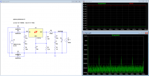
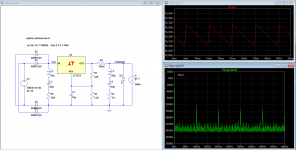
Here's a sim.
40000uF before the regulator. 100Hz is -128dB on the regulated output. Current draw from the LM317 is 500mA.
Here's another sim. This time with 20,000uF before the regulator.
100Hz is now about -120dB.
40000uF before the regulator. 100Hz is -128dB on the regulated output. Current draw from the LM317 is 500mA.
Here's another sim. This time with 20,000uF before the regulator.
100Hz is now about -120dB.
Attachments
- Home
- Amplifiers
- Power Supplies
- LM317 load capacitance