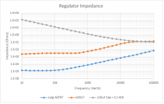
Take the impedance of what ever capacitor you want and overlay it on a graph of the regulator's output impedance.
a la:
Attachments
Hey, Threadjacker!!! WTF does this have to do with LM317 load capacitance??I was curious to know what was inside my analyser..........................................................
IMO The output impedance should correlate exactly with loop gain and the pass transistors Re. The frequency break point is adj pin capacitor Xc = gain setting resistor.
LM317s aren't all created equal, most vendor's don't change or update the specs to reflect their processes esp the ones going aiming for market share (why rock the boat). In TI's case they couldn't even copy the data sheets correctly.
ya look at Linear Techs ripple rejection curves and noise specs & so many other improvements they had to change the part number. http://cds.linear.com/docs/en/datasheet/lt0117.pdf
\designing band gaps is an art form, it doesn't help when they are on the same die with a big thermal gradient.
Rankings from STM, TI, On, & LT ..Reverse the lists order for the better parts.
Last edited:
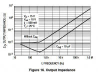
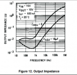
Here's one from TI:
Did you know that TI had that chart reversed for years, I hectored them into changing it.
Zout is inversely related to current drawn, so I would be disappointed if a TI LM317 had higher Zout @500mA than a Fairchild LM317 @140mA.
The load in all the tests was that used by Walt in his 1995 article, and the charts for LR, Noise and Zout correspond quite closely. So quod erat etc as the Romans used to say.
I have a tube of Fairchild 317s here. OMG. You are used to the fact
that the TO-220 tab is at least somewhat thick, so it can serve to conduct
a bit of heat. With Fairchild, it is a better foil, it fell off on one of the
first 4 I used. Bought at Digi-key or Mouser, so it's probably not a fake.
Gerhard
that the TO-220 tab is at least somewhat thick, so it can serve to conduct
a bit of heat. With Fairchild, it is a better foil, it fell off on one of the
first 4 I used. Bought at Digi-key or Mouser, so it's probably not a fake.
Gerhard
Last edited:
Hmmmm.....very interesting! The LT regulator is datasheeting ~10 db less noise than the T.I. or ON Semi part. About the same ripple rejection as the ON Semi. $2.50 apiece......I wonder which one Jan Didden used for his graphs....LM317s aren't all created equal, most vendor's don't change or update the specs to reflect their processes esp the ones going aiming for market share (why rock the boat). In TI's case they couldn't even copy the data sheets correctly. ya look at Linear Techs ripple rejection curves and noise specs & so many other improvements they had to change the part number. http://cds.linear.com/docs/en/datasheet/lt0117.pdf
Last edited:
Thanks, I had forgotten caps do not make Johnson noise.
What about other noise kinds ? I wonder about noise from the cap dielectric or some sort of granularity with current charging or discharging.
Some types of capacitors do have a ‘granular’ type of noise. Solid Tantalum will do this as it becomes formed to the operating bias. When small dielectric oxide areas short out because they are too thin, they are re-built by consuming Manganese Dioxide to make a new Tantalum Pentoxide layer. Each time that happens, the tiny micro-arc makes a tiny current spike. But, in this type of cap, these weak spots in the dielectric eventually go away as the cap fully forms to the applied bias voltage and no more weak spots remain.
Silver mica is also supposedly susceptible to a similar problem due to crystal defects in the mica insulator that allow conduction once the field gradient gets high enough near a defect. But, I’m not sure that there is any mechanism for them to disappear - there is no healing or dielectric film building mechanism in mica, as there is in Tantalum.
I have seen huge caps used on ultra low noise microphone preamps. Two caps at the input to DC isolate from phantom power. Huge caps because of overkill voltage. I never found the reason why, but I do know the designer knew what he was doing.
I guess this has to do with noise, any idea ?
An amplifier’s input current noise works into the combined source impedance at that input terminal and generates a voltage. If you use an oversized cap there, then the source impedance will be lower, and the generated voltage from the input current noise will be reduced. In a mike amp, the mike’s source impedance is in series with the P48 blocking cap. Typically, the mike amp presents a relatively high-Z bridging load, so WRT frequency response, the cap’s impedance can be a good bit larger than the source impedance of the mike, and still get a good low end response. However, the mike amp’s input current noise will be working (backward, toward the mike) into a much higher impedance than just the ~150Ω of the mike itself. So, it helps to make those caps oversized to reduce LF noise induced by the mike amp input stage current noise working into that source impedance.
Sorry for the thread drift, but IMHO it’s good to go over fundamentals like this. Eventually, it all becomes relevant (or needs to be discounted authoritatively) to get a well thought out design.
The LT regulator is datasheeting ~10 db less noise
LT317 for DIY is a 'no brainer'. High volume production is a trade-off the 'trimmed reference' vs adding another potentiometer.
Hey, Threadjacker!!! WTF does this have to do with LM317 load capacitance??
It has more to do with a LM317 than most things. The idea was to see if I could with very little use of money see if my mostly for fun 0R33 + 10 000uF could be working as a 1st order 48 Hz filter that could take the LM317 20dB below it's usual limits ( and seemingly 30 dB in ripple terms ). I note that others have speculated the same. So I have to ask you how is that not about LM317? It's 100% about LM317's and even more so ultra large capacitance. If we need to go to -150dB noise reference 12VDC I can not answer. I had a silly notion if we did 3.0103 x 2 x 24 = 144.5dB I might have done something good. I had the parts, I had the tools and the internet didn't know. I think you are saying a man who actually measures and makes things is not really a DIYer. As far as I know before this thread this subject has never been looked at in this detail. The reason I got involved is one day with not much else to do I took 3 x 10 000uF ( two before and one after ) a LM317 and 240R 2K1 + 470uF and saw where it went. Where is went was -132dB below 12V. My starting point was a 7812 giving -113dB. I speculate I possibly went to -150dB > 500 Hz. Just a numbers game really. For $4 it was not bad.
I was with my friend John last night who worked for SSL and still has a Pro Audio company. He says realistic noise levels could be - 100dB which translates to - 76dB due to how things work. John's recent work was magnetometers that require very low DC offset. He is not just a technician. He though my design goal a good idea. On the other hand he thinks a little hiss is often pleasent so one should choose. One can.
Last edited:
I think you are saying a man who actually measures and makes things is not really a DIYer.
It puts you in a great tradition of gentlemen scientists!
hahaWhen i read beyond 150dB, I reach for my gun.
when I see all these numbers go whipping around-n-around, he's delving into numerology books rather than science.
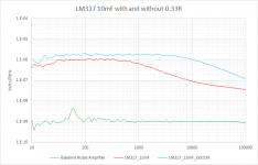
So the addition of a 0.33Ω resistor to a 10,000uF capacitor on the output of an LM317 added 20 db of noise at 10 KHz. I thought the original idea of adding the resistance was to rid the resonance caused by the low ESR of the large cap and this would lower the noise....????LM317 -- a Nat Semi original -- 10,000uF on output pin -- without and without 0.33R:
Yes, but I'll put those (appropriately) in another thread.@dotneck355
Is there anything else you want discussed?
BTW, it's dotneck335 not 355. The 355s had ebony fretboards and that silly stereo circuitry and weren't dotnecks anyway. The original dotneck335 is the holy grail of electric guitars, IMHO. But I drift off-topic!!
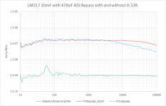
But who’d use a 10mF in a snubber?Here's a picture of the LM317 10mF combination with 470uF on the adjust pin. Again, the 0.33R resistor snubber on the 10mF electrolytic impairs noise performance.
- Home
- Amplifiers
- Power Supplies
- LM317 load capacitance