Yes they will all work. It is all a matter of degree's. Looking at it now I could have gone better (resistor hard up against the pin rather than out from it, but it's all diminishing returns I guess, and how much of a perfectionist you want to be.
Yeah, I wouldn't put those tiny heatsinks on any regulator unless it was going to power some simple op-amp circuit.
While you did bring up a valid point about the location of the 240 ohm resistor, I'm not a perfectionist and think at some point we have to draw the line and go with something.
If the 317 is that sensitive to say 10-12mm of extra distance from the output pin, perhaps I need to be looking for another positive regulator.
We can continue to move this-n-that on the board, but in the end is it really that beneficial?
Thank you for your input.
I expect the same deterioration in performance will apply to any three pin regulator.
It's why we see remote sensing for discrete regulators.
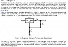
Note that the quote earlier (post71) stated that performance dropped by a factor exceeding 10times when 0r05 ohms was allowed between the sense point and the regulator output. It's the length of the output lead that affects this loss of performance.
As an aside, an 805 smd @ 1/8th Watt is operating at <10% of rating when 9.6mA is passing i.e. a 130r smd between the two lead outs does the upper resistor job when these two lead outs are adjacent.
It's why we see remote sensing for discrete regulators.
Note that the quote earlier (post71) stated that performance dropped by a factor exceeding 10times when 0r05 ohms was allowed between the sense point and the regulator output. It's the length of the output lead that affects this loss of performance.
As an aside, an 805 smd @ 1/8th Watt is operating at <10% of rating when 9.6mA is passing i.e. a 130r smd between the two lead outs does the upper resistor job when these two lead outs are adjacent.
Last edited:
Just go out the back of the pad with the sense resistor trace (the sense resistor can be located anywhere then), and shove the 317 leads all the way in to the pads (which will mean a larger pad hole to suit the widened lead near the package). Move the output cap as close to the device/heatsink as practical. That will give you text book performance.Yes an SMD resistor directly on the pads between the pins would be another good option Andrew!
Tony.
Just solder the smd direct to the lead outs. Not to the PCB.
Unfortunately the 337 (-ve reg) has these Out/Adj pins at the outside.
In this (-ve) case the smd is soldered direct to the OUT pin and a thin strand of copper from a stranded cable is soldered across to the far away ADJ pin.
A thin piece of insulation from a cat5 to insulate from the IN middle pin.
I expect the same deterioration in performance will apply to any three pin regulator.
It's why we see remote sensing for discrete regulators.
Note that the quote earlier (post71) stated that performance dropped by a factor exceeding 10times when 0r05 ohms was allowed between the sense point and the regulator output. It's the length of the output lead that affects this loss of performance.
As an aside, an 805 smd @ 1/8th Watt is operating at <10% of rating when 9.6mA is passing i.e. a 130r smd between the two lead outs does the upper resistor job when these two lead outs are adjacent.
I'm not going to try to solder 805 resistors. The smallest I use is 1206.
What exactly is the sense point?
Just go out the back of the pad with the sense resistor trace (the sense resistor can be located anywhere then), and shove the 317 leads all the way in to the pads (which will mean a larger pad hole to suit the widened lead near the package). Move the output cap as close to the device/heatsink as practical. That will give you text book performance.
I can't figure out what you're suggesting.
If I "go out the back of the out pad" I already have a diode between the input and output on the back side of the heatsink.
Can you draw on paper what you're talking and post a photo of it?
It's easy enough to move the 10uF caps back toward the regulators.
Just found the same thing Tony has been referring to about the resistor's location in a T.I. datasheet.
A Kelvin-like connection to the regulator's output terminal would minimize this problem.
Use a separate trace (from the opposite side of the output pad, where the top diode is)
to the feedback resistor.
Last edited:
Separate force and sense wires, see https://en.wikipedia.org/wiki/Four-terminal_sensing
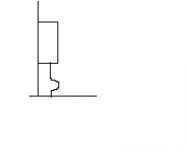
Regarding the heat sinking: please make sure that thermal expansion doesn't damage the regulator or the soldering. For example, make a bend in the leads.
In the attachment, the horizontal line is the PCB, the vertical line the heat sink and the box the regulator. When the lenghts of the leads and heat sink change due to thermal expansion, the bend will slightly change but there will be no large force on the soldered contacts or the IC package.
Attachments
Thinking about this some more, why can't you just solder a 1/8W axial lead resistor across the 337's leads(since they're spaced farther apart) and a 1206 across the 317's leads?
Yes!
Your advices is good in theory but I have never seen a regulator mounted in that way.
Why do you consider that relevant?
I've often seen components (not necessarily regulators) mounted on a heat sink attached to a PCB with no bends in their leads. Some of them had broken solder connections.
The sense point is the location where the voltage sensor taps into the output line. This applies to both the +sense tapping into the +output and to the -sense tapping into the -output. An LM317 has two sense points, one is at "ground/zerovolts" and is the -sense point....................
What exactly is the sense point?
post89 fig 16 shows the two sense points.
+sense is the black DOT at the top of R1.
-sense is the gnd symbol at the bottom of R2.
Last edited:
What is a Kelvin-like connection?
That's a method of reducing the effect of a current on a voltage measurement,
by choosing the voltage measurement points in a way that does not include
the voltage drop caused by the current. Usually four wires are needed for this.
https://en.wikipedia.org/wiki/Four-terminal_sensing
Last edited:
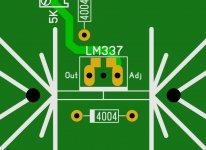
Guys, see what you think about my idea below of putting a 1206 resistor across the 337's pads. I know now I can always solder the resistors directly across the pins, but I'm not giving up on how to put them directly on the board also.
The 337 required a little more thought since the pins are on each end. So I put the 1206 on top of the board and made the center pad bottom layer only. That way the resistor can't touch or short it out in any way.
The 337 required a little more thought since the pins are on each end. So I put the 1206 on top of the board and made the center pad bottom layer only. That way the resistor can't touch or short it out in any way.
Attachments
- Status
- This old topic is closed. If you want to reopen this topic, contact a moderator using the "Report Post" button.
- Home
- Amplifiers
- Power Supplies
- LM317/337 Schematic Questions.