Are these Panasonic 10uF electros okay for using with LM regs.?
I don't see low ESR mentioned anywhere in their datasheet.
http://www.mouser.com/Search/Produc...0Ivirtualkey66720000virtualkey667-ECA-2AM100I
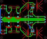
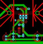
Also can someone please verify if my diode connections below are correct?
I always seem to get confused as to their orientation.
Thanks!
Diode direction is fine, but if your worried about noise then the traces to and from the large caps should be modified, and some RC snubbers for the secondaries may be advisable.
Indeed, the trace from the rectifier first to the cap and from there on to the rest.In your layout the ground side is ok but not the "live" side.Diode direction is fine, but if your worried about noise then the traces to and from the large caps should be modified, and some RC snubbers for the secondaries may be advisable.
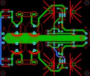
Made some change on one side, apply to the other side too.
If you put a capacitor between Adj and ground, best also a diode between Out and Adj to prevent the C to discharge via the LM317.Same principle as the diode between In and Out.
Mona
Attachments

Are these Panasonic 10uF electros okay for using with LM regs.?
I don't see low ESR mentioned anywhere in their datasheet.
http://www.mouser.com/Search/Produc...0Ivirtualkey66720000virtualkey667-ECA-2AM100I
LM317 datasheets normally recommend 25 uF when you use aluminium electrolytics, so the nearest E3 value would be 22 uF rather than 10 uF.
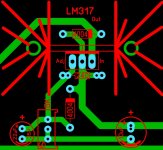
Mona, thank you for the suggestions and for actually showing me how to change the traces.
Does this look any better?
The adj circuit parts (cap and trimpot) that connect to main gnd trace should connect direct to their related output cap pad (along a discrete trace), and not somewhere along the main gnd trace.
You may want to add extra pads for the caps to allow different cap lead spacings.
Last edited:
LM317 datasheets normally recommend 25 uF when you use aluminium electrolytics, so the nearest E3 value would be 22 uF rather than 10 uF.
That's what I thought as well until bwaslo posted the following the article:
Simple Voltage Regulators Part 1: Noise - [English]
The adj circuit parts (cap and trimpot) that connect to main gnd trace should connect direct to their related output cap pad (along a discrete trace), and not somewhere along the main gnd trace.
You may want to add extra pads for the caps to allow different cap lead spacings.
Does this look better?
Attachments
Rectifier Diodes.
Back to rectifier diodes...would these 1A Schottky SB180s be a good choice or go with the MUR220s?
http://www.mouser.com/Search/ProductDetail.aspx?R=SB180virtualkey51210000virtualkey512-SB180
Back to rectifier diodes...would these 1A Schottky SB180s be a good choice or go with the MUR220s?
http://www.mouser.com/Search/ProductDetail.aspx?R=SB180virtualkey51210000virtualkey512-SB180
Does this look better?
Yes that layout is preferred to minimise regulated output noise.
Schottky's have a relatively high off-state capacitance.
If you were keen, and had the instrumentation, you could try and make a comparison measurement between those schottky, and fast UF or MUR types, and even including bell-ringer snubbing the transformer secondary. Depending on how well you layout the transformer, and any test instrumentation, you are likely to measure no difference.
Much better.Does this look better?
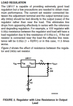
The voltage sensing of the regulator must not get contaminated by voltage drops along a long non zero resistance/impedance trace.
True Andrew, but it would be even better if the 240 ohm resistor was moved so that the output side was right next to the output pin of the reg. In my PS I soldered it direct to the output Pin on the reg above the pcb...
Attached is the relevant part from the National Semiconductor datasheet.
Tony.
Attached is the relevant part from the National Semiconductor datasheet.
Tony.
Attachments
True Andrew, but it would be even better if the 240 ohm resistor was moved so that the output side was right next to the output pin of the reg. In my PS I soldered it direct to the output Pin on the reg above the pcb...
Attached is the relevant part from the National Semiconductor datasheet.
Tony.
Are suggesting switching the diode and 240 ohm resistor's positions from where I have them now?
If not, how about posting a photo of what you're talking about?
ah OK you have board level heatsinks. I didn't think too much about my heatsinks (I under-estimated). They were fine when I first started (as I only needed around 50mA but when that increased to 250mA I had to uprate the heatsinks, and it was a challenge due to the tight placement on the board.
You could mount the resistor on the reverse side of the board though")
You could also vertically mount the resistor directly between the pins, just make sure the output end is the end with the resistor sitting against the board.
Tony.
You could mount the resistor on the reverse side of the board though
You could also vertically mount the resistor directly between the pins, just make sure the output end is the end with the resistor sitting against the board.
Tony.
Last edited:
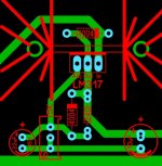
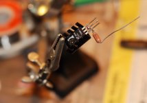
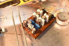
Yes they will all work. It is all a matter of degree's . I found a pic of what I did. Looking at it now I could have gone better (resistor hard up against the pin rather than out from it, but it's all diminishing returns I guess, and how much of a perfectionist you want to be.
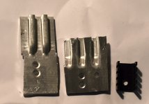
My layout was on vero board, and I would do things differently now if I were to do it on a proper PCB. Note those heatsinks were marginal at 50mA I had to replace them for 250mA!! 2nd pic, one in the middle is what I used, cut down SMPS heatsink from a dead computer power supply... Was the only way I could get something to fit I obviously neglected that side of things in the original layout considerations....
Tony.
. I found a pic of what I did. Looking at it now I could have gone better (resistor hard up against the pin rather than out from it, but it's all diminishing returns I guess, and how much of a perfectionist you want to be. My layout was on vero board, and I would do things differently now if I were to do it on a proper PCB. Note those heatsinks were marginal at 50mA I had to replace them for 250mA!! 2nd pic, one in the middle is what I used, cut down SMPS heatsink from a dead computer power supply... Was the only way I could get something to fit
I obviously neglected that side of things in the original layout considerations.... Tony.
Attachments
Last edited:
- Status
- This old topic is closed. If you want to reopen this topic, contact a moderator using the "Report Post" button.
- Home
- Amplifiers
- Power Supplies
- LM317/337 Schematic Questions.