Nothing to do with unequal rails and nothing to do with unequal clipping............... I observed that with a previous try with LM3886, one bat give 13 v and other 9,5 v, some distorsions appeared, then amp stop..................
Read the datasheet for the 3886
The -ve input detects low rail voltage and switches OFF. ~-9Vdc.
The mute needs current into/out of it's pin.
Again low voltage will pull the 3886 into mute, or partially muted condition.
Read the datasheet for the 3886.
Last edited:
Hi all,
Thank's Daniel for single rail schematic..
I think we can use TDA2050 instead 1875, with same values ?
Only problem I saw : 4700 uF ! What quality, can be used bipolar ?
I'm always happy with my build, batterie life is near 12 hours, amp stop when voltage is 6,5 volt, and just before I don't ear any distorsions like with LM3886.
It will stop abruptly..
I kept 4800 uF (1800+1800+1200), more uF damaging the mid..
I'm thinking about a filter batterie, cause chemical work must generate some noise.
What about schematic below .
Phil.
Attachments
Yes, it is cross compatible to most 5 pin amplifiers.Hi all, Thank's Daniel for single rail schematic. I think we can use TDA2050 instead 1875, with same values? Only problem I saw : 4700 uF ! What quality, can be used bipolar?
Output cap for single rail amp is an ordinary polar cap (as it is marked on the schematic). The voltage capacity of that cap is same as for any on the power circuit (or if you had to guess, it is 63v when if the voltage isn't known).
Best bypass cap for 1800u||1800u is in fact 1800u, not 1200u.I kept 4800 uF (1800+1800+1200), more uF damaging the mid.
You need a series element (to serve ballast) between any different size cap loads on your power circuit. Otherwise you've got a setup like a Clydesdale teamed with a Shetland for a cart that only goes in circles. When that happens with DC power, we'd call it ringing, and yes, that can affect your midrange.
Another factor is recuperating/recovering the reservoir capacitance quickly enough for audio use (charge is lost to move the speaker, each time). I have a very approximate rule of thumb: VA*123=maximum microfareds per each rail. If your power supply is in watts then it is approximately W*111=maximum microfareds per each rail. Dull audio can happen if there's too much capacitance for a given power supply mainly because the cycle of regaining and losing and regaining the charge again is too slow if the estimates are exceeded. I have no idea what the estimate would be for single rail.
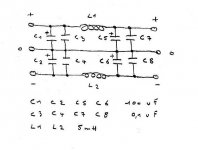
CLC is quite successful, but inductors were once popular for high end tone controls, because same thing. A small value inductor will probably be okay and is generally useful for scraping off some of the high frequency bridge rectifier switching noises of linear supplies.I'm thinking about a filter batterie, cause chemical work must generate some noise. What about schematic below. Phil.
In some cases where the needed inductor value is very large and the current is smallish, a gyrator, also known as a capacitive multiplier, may be less expensive than so much copper. Generally, in such rare cases, the copper expense still results in somewhat better performance than the active circuit, with the main differences of costs and availability.
Generally, the spots to put inductors are fairly well known, but here's a summary.
Power, L, smoothing cap, L, reservoir capacitance, L, decoupling capacitance, L, HF Bypass capacitance.
Well, very much why they have different names is that they require ballast between them, mainly because they are of different sizes. In most cases, some resistance would do; however, other elements, such as inductors, will do if their resistance to a particular frequency happens to be suitable.
In this description, L (inductors) are also serving up ballast so that the different size cap loads don't battle (otherwise pointless to use the inductor). The resistance is mandatory, but the inductors really aren't unless/Except for when those could be more helpful. . . such as high resistance to undesired frequency and very low resistance to desired frequency (which is when you'd want an inductor).
Inductors certainly aren't the only series elements that can be used to separate those bits.
I wish that I knew how to generate enough handy "rules of thumb" to cover all of this, and I don't; but, just bear in mind that all of these locations have a different name for the reason that they should be separated at least enough (of either resistance or selective resistance) to justify different naming.
Last edited:
Hi,
Thank's Daniel, I had not done enough attention to your post 103.
I must will order some new caps, and make 2200//2200 uF..
I would build as my schematic for filter and see what's happen.
Today, I listen with full batteries powererd : pc > dac > amp
It's amazing, I had never heard much music, it seems that a magician add notes and sounds in my files..
Phil.
At low gain, the LM675 is more relevant for battery powered amplifier.
LM1875 is Class AB, but LM675 is Class aB. Have a look at the datasheet charts that list the amount of power used when not running a speaker.
The low bias LM675 is also pre-compensated for lower gain, so that the distortion figures are not significantly different. . . but the usable closed loop gain figures are.
Also, there's some LM675 and other supporting bits gathered on my desk because that's my next project. I've never before made a low gain amp on purpose. However, I think that a fair start on such a thing would be one that is supposed to do it.
- Status
- This old topic is closed. If you want to reopen this topic, contact a moderator using the "Report Post" button.
- Home
- Amplifiers
- Chip Amps
- LM1875 P2P "solar powered"