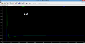
I just tried the circuit in simulation again. Just try altering C2 for a start. It should all work.
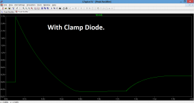
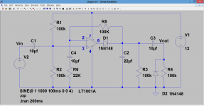
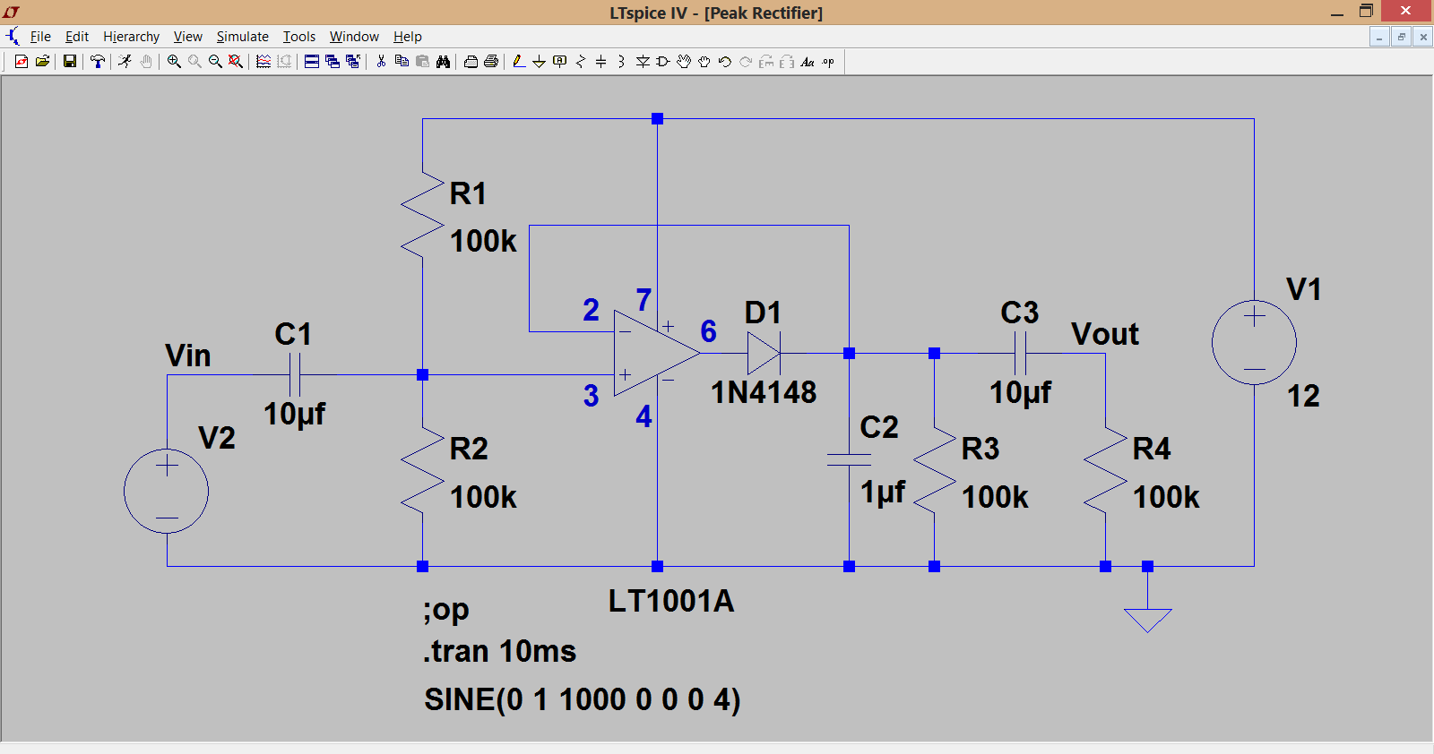
(it could be worth adding a 'clamp diode' across R4 as shown here to limit any negative going transients)
(it could be worth adding a 'clamp diode' across R4 as shown here to limit any negative going transients)
Attachments
can i add you on skype or something? will be faster to discuss
On the forum like this is fine
") It helps others too.
It helps others too.Like i have no idea what should happen if i change c2. I have no voltmeter or something.
and i did this
http://www.diyaudio.com/forums/atta...20987547-lm-3915-vu-meter-problem-circuit.png
everything seems fine but i have no idea where to connect C1. The positive in my circuit is connected to pin 3 and negative doesnt connect anywhere.. ;/ so where do i put it?
and i did this
http://www.diyaudio.com/forums/atta...20987547-lm-3915-vu-meter-problem-circuit.png
everything seems fine but i have no idea where to connect C1. The positive in my circuit is connected to pin 3 and negative doesnt connect anywhere.. ;/ so where do i put it?
You need a multimeter.
C1 is the input coupling capacitor. The 'live' audio input comes in at the left side of the cap. The ground of the audio input (the shield on the wire) goes to ground.
The markings on the opamp are confusing you. The + and - are not voltage supplies but the standard designators for the non inverting and inverting inputs. The power supply goes to pin 7 of the opamp (for a 741) and the negative supply to pin 4.
i could be wrong but i think that the OP complaint is that he's getting dot mode and not a bar graph display if pin 9 on the LM 3915 is not tied to V+ he would be in dot mode with rapidly blinking/shifting states and on a breadboard that's a likelyhood that only a meter can confirm.
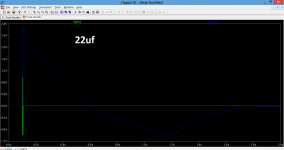
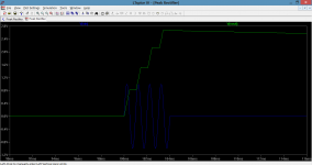
So you need to prove the opamp circuit. The pictures I posted earlier today show the output of the opamp circuit when fed with a just 4 cycles of an input signal. Here it is in detail. 1 volt peak at the input, and that is rectified, amplified and held. You can see the output (green trace) climbs to nearly 2.8 volts and then falls away slowly. This is with a 22uf cap for C2 to hold the voltage for a bit longer.
It should all work if constructed correctly.
It should all work if constructed correctly.
Attachments
- Status
- This old topic is closed. If you want to reopen this topic, contact a moderator using the "Report Post" button.
- Home
- General Interest
- Everything Else
- lm 3915 vu meter problem.