If we accept this definition of "unconditionally stable" (an amp stable at any closed loop gain), then a "conditionally stable amp" like yours will always have some pulse response overshoot (such a "conditionally stable" amp is necessary an at least second degree underdamped system - see the phase response with a dip before ULG, this phase dip is what creates instabilities at e.g. low CLG). This overshoot can be tamed using an input filter, but then it is not realistic to expect, in simulation or practice, perfect step response without one.
That is what I thing also. Do you accept my previous square wave test, with input filter connected, correct?
dado
If we accept this definition of "unconditionally stable" (an amp stable at any closed loop gain), then a "conditionally stable amp" like yours will always have some pulse response overshoot (such a "conditionally stable" amp is necessary an at least second degree underdamped system - see the phase response with a dip before ULG, this phase dip is what creates instabilities at e.g. low CLG). This overshoot can be tamed using an input filter, but then it is not realistic to expect, in simulation or practice, perfect step response without one.
If you knew the answer , why ask the question.??..

Unconditional stability as noticed by Dadod is not strictly necessary
for amps provided they are set at high enough CLG , yet , it is better
to have the highest possible phase margin as capacitive loading will
not only increase the phase dip abut also , consequently , induce
a local gain peak , hence reducing the gain margin.
If you knew the answer , why ask the question.??..
Unconditional stability as noticed by Dadod is not strictly necessary
for amps provided they are set at high enough CLG , yet , it is better
to have the highest possible phase margin as capacitive loading will
not only increase the phase dip abut also , consequently , induce
a local gain peak , hence reducing the gain margin.
Yes, that is well said. I like to hear different opinions and different suggestion. The pudding is in details.
dad
In principle such a computation is made without the input high frequency
attenuation capacitor and without output LR filter, this to check if the amp
is unconditionaly stable.
Indeed , most amps rely on theses filters to be stable as conditionnaly
stables amps allow to reduce THD by the virtue of greater HF loop gain.
If you knew the answer , why ask the question.??..
Because, as you claimed above, I disagree that the input filter has anything to do with the amp stability, conditionally or not.
That is what I thing also. Do you accept my previous square wave test, with input filter connected, correct?
dado
The pulse step response, considered as a consequence of the gain-phase characteristic result, is not an independent determination. It is mathematically related to the complex CLG transfer function, e.g. by simply mapping the Fourier transform H(jw) to the Laplace transform H(s) through jw->s and calculating the H(s)/s reponse.
Now, as I said, there could be some large signal implications of the pulse step response (like, as a notable example, slewing effects). Such effects are generally not very well modelled in Spice, as they usually may involve non linear saturation effects in active devices and other non-linear effects that may be poorly (or not at all) included in the device models. The same non-linear effects may induce transient instabilities, but again, these have little to nothing to do with the linear gain-phase responses determined using ac analysis in Spice. To avoid such large signal instabilities, indeed an input filter could be effective, but I still see this as a poor man's stabilizing method.
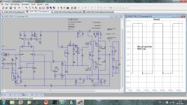
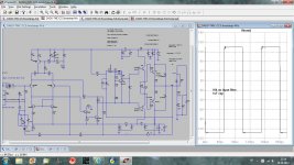
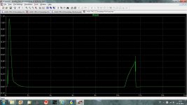
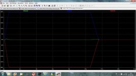
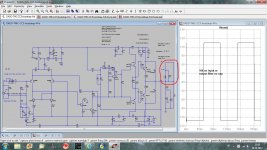
Here is 10kHz square wave simulation without input filter and with and without output filter.
The zobel is changed now, I use 2R7 and 100nF now. Output inductance is 1uH parallel to 2R7 resistor.
dado
The zobel is changed now, I use 2R7 and 100nF now. Output inductance is 1uH parallel to 2R7 resistor.
dado
Attachments
-
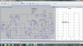 square10k-no-input-or-output-filter.jpg269.8 KB · Views: 363
 -
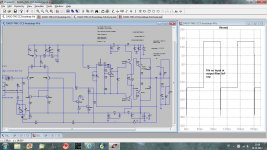 square10k-no-input-or-output-filter-5nF.jpg254.4 KB · Views: 354
 -
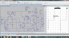 square10k-no-input-or-output-filter-10nF.jpg259.4 KB · Views: 329
 -
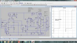 square10k-no-input-filter-10nF.jpg249.5 KB · Views: 319
 -
 square10k-no-input-filter-100nF.jpg259.5 KB · Views: 300
 -
 square10k-no-input-filter-1uF.jpg252.5 KB · Views: 128
Have you adjusted the slew (risetime) of the test sq?
I don't understand you captions.
Some plots say no output filter, but I see the Thiele Network always connected.
I use 20 nsec now.
By output filter I mean an inductance parellel with a resistor. Zobel should always be connected(this is my opinion) and I shorted the inductance for those tests.
dado
I can't see the short across the L.I use 20 nsec now.
By output filter I mean an inductance parellel with a resistor. Zobel should always be connected(this is my opinion) and I shorted the inductance for those tests.
dado
Tap the output before the L or after the L.
I would only investigate by tapping before the L, I cannot recall advice to investigate a particular operation by tapping output after the L.
I can't see the short across the L.
Tap the output before the L or after the L.
I would only investigate by tapping before the L, I cannot recall advice to investigate a particular operation by tapping output after the L.
Look carefuly first three screen shots and compare for the rest.
I still cannot see a short across the L.
I can see that sim1 shows the C across the load disconnected.
Do you get a warning that a component has an unterminated end?
Look here again!
No worning, LTspice allowes one side of a component left not connected.
Attachments
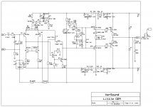
![Little-GEM-T-mk2.LAY].jpg](/community/data/attachments/296/296334-99ca2d3727393df1c0cde46cc533e9cf.jpg)
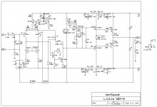
![Little-GEM-N-mk2.LAY].jpg](/community/data/attachments/296/296341-be450f028f1dc1b8167c0d8c924a155c.jpg)
No worning, LTspice allowes one side of a component left not connected.
Take a look at the Spice Error Log, there should be warnings for floating nodes.
Thanks
-Antonio
Take a look at the Spice Error Log, there should be warnings for floating nodes.
Thanks
-Antonio
Yes I remember that now, I have seen it. Thanks
- Status
- This old topic is closed. If you want to reopen this topic, contact a moderator using the "Report Post" button.
- Home
- Amplifiers
- Solid State
- Little GEM