Excuse me... How can such "thing" be called a high-end amplifier with a price tag of almost $9000 
I mean ... I'm looking at a gorgeous Luxman M-02 power amp at the moment and I know what is inside and how its designed. Honestly, comparing those two amps looks to me like comparing a 20 year old Ferrari and a brand new Ford Fiesta(with the Fiesta being the Linn). It just doesn't make any sense to me...
I mean ... I'm looking at a gorgeous Luxman M-02 power amp at the moment and I know what is inside and how its designed. Honestly, comparing those two amps looks to me like comparing a 20 year old Ferrari and a brand new Ford Fiesta(with the Fiesta being the Linn). It just doesn't make any sense to me...
Indeed that's what I thought too, looks like some ST micro chip, unless they have ST make them for them.
yep, just looks like ST, i considered whether they had contracted them to produce it for them, but i find it doubtful, any company that really did spend years 'developing' a 'new ultra-linear ic technology' would generally get their own name printed on it. the moq would be so high to do that, that you would think they would throw such a service in.
nope and i better watch my words here, it looks to me to be more of a case of 'mutton dressed as lamb'
That's what Linn do. They call stuff names so as to attach exorbitant price tags on it. Texans call it "bull". That's why I like Texans.Excuse me... How can such "thing" be called a high-end amplifier with a price tag of almost $9000
ST would be perfectly happy to do a "selection" of a standard part or even a bond out modification for a definite supply contract of several thousand parts.
I am just puzzled that they managed to get a patent for something very similar to Peter Walkers now expired patent
The circuit should work well enough
I am just puzzled that they managed to get a patent for something very similar to Peter Walkers now expired patent
The circuit should work well enough
Interesting approach.The patent says:
"UK Patent Application GB 2405275 A"
date od Publication: February 2nd, 2005
Follow question rises up:
which exact influence makes the use uf the serial inductors in the emitter line?
Particularly of interest is the fact, that the output power devices at this approach are inside of the NFB loop (in opposite to the STASIS power amp topology - here is the output power stage outside of the NFB loop and the use of inductors there give only the effect of a low pass character).
Full disclosure is a must. The inventor knows this rule. He/she may be denied the invention if violated.Hi Jo!
The inductor is connected to the emitter,you are right. But the transistors could still be connected as in the other thread (but I'm not sure). They always try to hide things in patents and with the TDA7293 it really works well to put the bipolars there. Can't anyone check this on their chakra amp?
Hi tiefpassuebertr,
The patent describes the effect of the inductors as follows:
"for extending a switching off period of the second amp (with the bipolars) to smooth any switching discontinuity".
I conclude from this that the bipolars are switched off with a slight delay, if current output of the TDA7293 would be enough; by this in a practical situation of dynamic music the bipolars are not always switched on and off and on and off ..., but are kept on for a longer time to smoothen the current output and eliminate the side-effects of the on/off switching of the bipolars.
Hi,
I assume the Linn Chakra circuit is the one in the patent drawing. It is an interesting apporach.
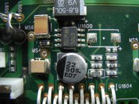
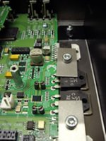
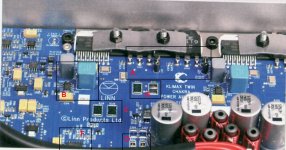
What really interests me is the purpose of the opamp in front of the TDA. This dual opamp can be found in every Linn amp, including the Sneaky DS (which does not have the Chakra circuit). I will attach a foto of the Sneaky DS, a Chakra 500 Twin and a Majik I.
I guess it is a DC-Servo, but I am not shure.
What do you think ?
jo987
I assume the Linn Chakra circuit is the one in the patent drawing. It is an interesting apporach.
What really interests me is the purpose of the opamp in front of the TDA. This dual opamp can be found in every Linn amp, including the Sneaky DS (which does not have the Chakra circuit). I will attach a foto of the Sneaky DS, a Chakra 500 Twin and a Majik I.
I guess it is a DC-Servo, but I am not shure.
What do you think ?
jo987
Attachments
This is exactly what is done in every Quad design from the 405 and the 306. There are inductors around the dumper devices to smooth the switching discontinuities. These inductors should not be confused with the main inductor in the output bridge circuit.Hi tiefpassuebertr,
The patent describes the effect of the inductors as follows:
"for extending a switching off period of the second amp (with the bipolars) to smooth any switching discontinuity".
I conclude from this that the bipolars are switched off with a slight delay, if current output of the TDA7293 would be enough; by this in a practical situation of dynamic music the bipolars are not always switched on and off and on and off ..., but are kept on for a longer time to smoothen the current output and eliminate the side-effects of the on/off switching of the bipolars.
What a total bollocks Patent application - talk about reinventing the wheel! its just Basic text book "Current Dumping"!
Edwins A+AB WirelessWorld artificial back in about 1971 "Invented" or at least the first time I'd seen principle, with Quad taking the idea one stage further and used a Bridge circuit to linearise the forward Gain as the "Current Dumpers" contributed to the transfer gain.
As David has already said, Quad (and others) uses Inductors in the Emitters to "shape" the crossover region between devices since the very early days when supposedly "complementary devices" where anything but - or in the case of the mentioned Quad designs the use of Quasi complementary output stages...
It says volumes about Linns designer "William Miller" that he's tried to patent a well known basic circuit topology... I suggest he learns a little more about basic audio design first before believing he's invented anything clever....
Last edited:
For Reference:-
The Basics of Current Dumping is introduced in JLH "Audio Electronics Reference Book" pg. 423 (Fig 14.25 "The Basic Current Dumping System").
Also Piet Lambrechts Edwin A+B article a referenced to in my above post was Republished in The Audio Amateur Issue 3 1972 having been "Adapted with permission, from an article originally Published in Elektuur Magazine".
Deltec / DPA "Compounded ClassA" power amplifier designs where based on this OPS topology.
Was this Linn Patent ever granted?
Did this patent application [GB 2,405,725A] ever become a granted patent? Once this application was filed in 2004 [there was also a 2003 priority date], Linn Products Limited began practicing its proposed invention with possibly a Patent Pending caution flag to deter others from practicing it. Linn already has 10 years of "reduced to practice" amps under its belt. However, if it was granted, then we're all reading a chorus in the previous posts "how did this grant ever pass" despite all of this possible prior art knowledge, and published information?
Did this patent application [GB 2,405,725A] ever become a granted patent? Once this application was filed in 2004 [there was also a 2003 priority date], Linn Products Limited began practicing its proposed invention with possibly a Patent Pending caution flag to deter others from practicing it. Linn already has 10 years of "reduced to practice" amps under its belt. However, if it was granted, then we're all reading a chorus in the previous posts "how did this grant ever pass" despite all of this possible prior art knowledge, and published information?
Patent of Linn Products Limited
Granted to Linn Products Limited; inventor William Miller as shown in the published attachment.
Best regards
Did this patent application [GB 2,405,725A] ever become a granted patent? Once this application was filed in 2004 [there was also a 2003 priority date], Linn Products Limited began practicing its proposed invention with possibly a Patent Pending caution flag to deter others from practicing it. Linn already has 10 years of "reduced to practice" amps under its belt. However, if it was granted, then we're all reading a chorus in the previous posts "how did this grant ever pass" despite all of this possible prior art knowledge, and published information?
Granted to Linn Products Limited; inventor William Miller as shown in the published attachment.
Best regards
Attachments
Hello. I did not see a value for their inductance. The site showed graphs of their impedance as a function of frequency starting at ~0.5 MHz. Maybe a DIYer has an answer.Those inductors are ferrite beads.
MURATA|BL02RN2R1M2B|FILTER, EMI, 7A, RADIAL, DOUBLE | Farnell United Kingdom
Best regards
- Status
- This old topic is closed. If you want to reopen this topic, contact a moderator using the "Report Post" button.
- Home
- Amplifiers
- Chip Amps
- Linn Chakra power amps revealed ...