If you're driving 80KΩ, or your 10K attenuator, the LME49990 will do that just fine by itself - it does have an output stage, and it can drive 600Ω. Don't overcomplicate things. Choose a simple circuit, make a competent layout, use a good supply and bypassing, and be happy. This is not tough, nor does all of this 'excess effort' need to happen.
Humans tend to overcomplicate simple tasks and oversimplify complex tasks, according to their abilities to 'do stuff'. Don't fall victim to this - the answer is actually a simple circuit.
Humans tend to overcomplicate simple tasks and oversimplify complex tasks, according to their abilities to 'do stuff'. Don't fall victim to this - the answer is actually a simple circuit.
Last edited:
inverting output means the op amp input Voltage is fixed, since it doesn't move then the input common mode effects I mentioned are not excited - so use inverting for removing a last little bit of op amp distortion
but since you have a load current you may get some added output stage nonlinearity and self heating gain modulation
inverting with a composite op amp, separately packaged buffer in the feedback loop cuts the thermal feedback, can be as good as the bootstrapped composite
but since you have a load current you may get some added output stage nonlinearity and self heating gain modulation
inverting with a composite op amp, separately packaged buffer in the feedback loop cuts the thermal feedback, can be as good as the bootstrapped composite
inverting output means the op amp input Voltage is fixed, since it doesn't move then the input common mode effects I mentioned are not excited - so use inverting for removing a last little bit of op amp distortion
but since you have a load current you may get some added output stage nonlinearity and self heating gain modulation
inverting with a composite op amp, separately packaged buffer in the feedback loop cuts the thermal feedback, can be as good as the bootstrapped composite
???
Hi Keruskerfuerst,
jcx is right on the money and said what I was about to say. The thermal effects that involves the gain stage (even if it is unity gain) are easy to avoid. There is a very good reason why composite op amps are used. The inverting configuration avoids common mode distortion effects as the inputs see no more than a few mV worth of signal. That's why jcx said that the input level is constant. For all intends and purposes, that statement is correct.
-Chris
I collected a few composite op amp circuit ideas in one thread:
Walt Jung has long been an advocate of 2 op amp (or op amp + buffer) composite circuits and points out their advantages – check his web site; “Op amp Audio” series
Gerald Graeme has also advocated 2 op amp composite amplifier, with high loop gain from 2 pole responses – “Amplifier Applications of Op Amps” 1999 devotes a chapter to composite op amp circuits and their compensation
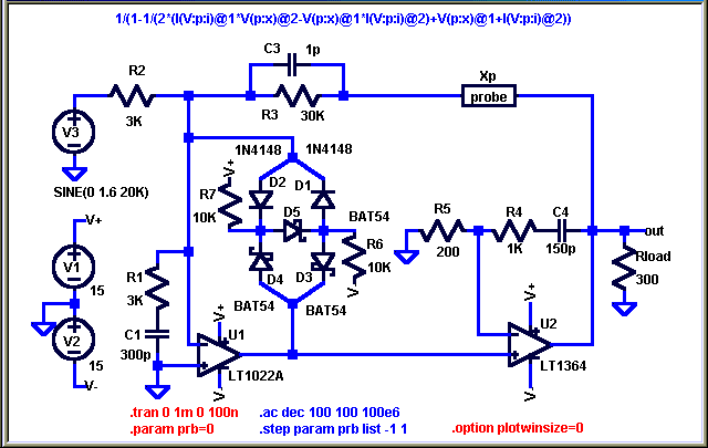
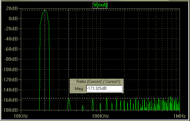
This sim circuit topology is close to circuits I have built and I have verified that they can achieve measured 1KHz harmonic distortion (and 1KHz IMD from 1:1 10KHz + 11KHz) below my 160dB instrumentation limit

Composite amplifiers can reduce active device contributions to audio frequency distortion to unmeasurable levels (1 V input, 20 KHz sim results: )

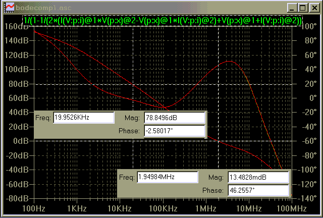
The output op amp is a modified integrator that provides large audio frequency gain, those in the know will object that the loop phase response, which exceeds 180 degrees around 100 KHz invites oscillation or poor recovery from clipping

(the Loop Gain Probe is available from the LtSpice Yahoo group files area - just cut it out and delete .prams lines if you don't want to use it)
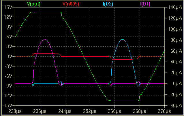
The clipping response is greatly improved by the symmetrical clamping diode bridge that holds the input op amp to +/- 1 V output when the output op amp saturates, this means that the input op amp is held in its linear operating region, its contribution to loop gain and phase shift is minimized, and its output only has to slew ~ 1V to when recovering from saturation ((1.6 V @ 20 KHz input, V(n005) is Lt1022 output)

Simple back-to-back diodes would also provide for the improved clipping response, but the bridge reduces diode capacitance and nonlinear conduction current that add directly to the feedback error voltage and cause nonlinear distortion
(distortion and phase margin # may be off slightly, I plotted those with all 1N418 diodes before it occurred to me to reduce clamp voltage with Schottkys, this means diode feedthru may be slightly higher due to higher capacitance form lower reverse bias on D1,2)
Hi Keruskerfuerst,
jcx is right on the money and said what I was about to say. The thermal effects that involves the gain stage (even if it is unity gain) are easy to avoid. There is a very good reason why composite op amps are used. The inverting configuration avoids common mode distortion effects as the inputs see no more than a few mV worth of signal. That's why jcx said that the input level is constant. For all intends and purposes, that statement is correct.
-Chris
Really?
Yes, really.
Op amp theory. The non-inverting input is ground referenced (or some common voltage level). The op amp will try to make both inputs the same instantaneous voltage, so the inverting input will be very close to the same instantaneous voltage that the non-inverting input is sitting at. In this case, common ground. In a non-inverting configuration the inverting input will follow the input signal level on the non-inverting input. Chasing it all over its common mode range.
See?
I did a lot of opamp based buffer listening in the passed, and the one for me that always came up trumps was the AD825 even at unity gain.
It always sounded more dynamic an punchier and uncoloured, and if implemented well smooth and crisp.
Fet input and bipolar output. Pity it doesn't have dc offset nulling pins to null out any dc coming into it from the source, as it gives vey low dc offset itself.
Cheers George
It always sounded more dynamic an punchier and uncoloured, and if implemented well smooth and crisp.
Fet input and bipolar output. Pity it doesn't have dc offset nulling pins to null out any dc coming into it from the source, as it gives vey low dc offset itself.
Cheers George
Hi George,
Thanks for the hint with AD825. In principle the unity gain buffer PCB that I plan to design can use both LME49990 and AD825 because they have the same package. This could be something to try but as I stated earlier I will not be able to decide based only on listening test and I am not ready to invest into an expensive measuring tools.
I do think that the circuit for audio reproduction should have no sound coloration in any way. If someone wants to "color" the sound in the way he likes it is always possible to do with the dedicated device giving full control of the situation.
This is why the op-amps with the distortion figure beyond fourth digit after comma are very attractive to me (LME chips). While AD825 datasheet seems to only provide data relevant for high frequency (MHz range) applications and nothing related to audio range... And I personally have very limited knowledge of parts on my own. So if you could point me where audio range related data for AD825 is discussed it will great.
Regards,
Oleg
- Status
- This old topic is closed. If you want to reopen this topic, contact a moderator using the "Report Post" button.
- Home
- Source & Line
- Analog Line Level
- Line level buffer: discrete or ICs based?