Advice for Newbs:
- Get the 2 PDF Files which are kindly put together from a member. In these documents he enlisted the topics and where these are posted in the thread. They are some basics advices for matching in the 2nd PDF.
The PDFs were posted several times in the Thread - just go in the print-thread mode......show all posts and search for the PDF.
You STILL have to read the Thread, with or without a 9yo boy, this is the requirement of DIY.
Goerge offers ready-built Kits - send him a PM or email.
cheers
Alan
georgehifi said:Very nice Zen Mod, you have been busy, obviously not married.
Cheers George
naah George ........ it was easy ........ because :
1. you prepared needed know-how
2. my friend spavleski and me - we are pretty used to multitasking ;
2a. even if we both are married , with small kiddoes ; maybe *2* is because of *2a* ?

tnx again !
Attachments
georgehifi said:Hey that looks like my work bench, even down to the old piston for ashtray, two years ago. I gave up got, fatter and still love the smell of a freshly lit one.
Cheers George
so - besides that what's shown in your avatar , seems that we have few more common things
")
I miss McCoy , too ;(
Remote control
Hi folks,
Thats five signed up for the VCCS board for remote control interface of Lightspeed.
I like the simplicity if the Holtek chip interface with the DS1802. I have decided to use this in my system. The chips are readily available from a variety of sources at very low cost, unlike the Rapid kit which is out of stock at present, with a lead time approaching two months, and there are no programming hassles for constructors. The Holtek application note is clear and easy to follow for scratch builders. I can easily add PCBs for the transmitter and the receiver to the VCCS order when the time comes. If any one is interested in having these boards, in addition to the VCCS board, let me know.
I am having problems answering e-mails at present requesting technical information. Sorry it is just lack of available time. To save me repeating answers many times can you post your questions on this thread. You can also express your interest in boards or modules on the thread. This will give a real time view of the level of interest an may encourage an earlier order for the boards.
Regards
Paul
the Maximus VCCS
Um Paul,
It may be worth leaving those drive transistors in the pcb design so that if we want to expand the Vol Control for balanced use, can just add the transistors for the extra LDRs - yes?
ZenMod,
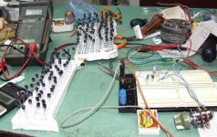
just how many LDRs did you get - it looks like a couple of hundred!
And I see you've measured them one by one, too - is it a Zen thing?!
Interesting Cct.
Um Paul,
It may be worth leaving those drive transistors in the pcb design so that if we want to expand the Vol Control for balanced use, can just add the transistors for the extra LDRs - yes?
ZenMod,
just how many LDRs did you get - it looks like a couple of hundred!
And I see you've measured them one by one, too - is it a Zen thing?!
Interesting Cct.
Re: the Maximus VCCS
dunno yet ;
main goal is achieved - constructed gadget and covered local forum GB .
if someone else is interested , I can calc prices for small batch (and post HERE
), but I already know that prices can't be so popular , counting on shipping , customs (outgoing Customs - from Serbia) etc .
hardly that these two pcbs (balanced PSMLS and balanced jfet buffer ) can go for less of 45E - 50E , counting from top of my head .
172 , precisely ;
that was mucho of manual work , not counting needed concentration ....
certainly Zen thing
ondesx said:Hello Zen Mod,
Any PCB available ?
ATB
dunno yet ;
main goal is achieved - constructed gadget and covered local forum GB .
if someone else is interested , I can calc prices for small batch (and post HERE
), but I already know that prices can't be so popular , counting on shipping , customs (outgoing Customs - from Serbia) etc .
hardly that these two pcbs (balanced PSMLS and balanced jfet buffer ) can go for less of 45E - 50E , counting from top of my head .
jameshillj said:......
ZenMod,
just how many LDRs did you get - it looks like a couple of hundred!
And I see you've measured them one by one, too - is it a Zen thing?!
Interesting Cct.
172 , precisely ;
that was mucho of manual work , not counting needed concentration ....
certainly Zen thing
Thanks for your explanation - that is really helpful.ondesx said:I ordered and built the OptiVol from Greg Ball. It's a NSL 32 too, but an hybrid one (not a series-shunt like the George Lightspeed MKII). It works pretty good but I experienced a very low output level. Things are bettered using his VBuffer (or any buffer you may have, i. e. an OP AMP in follower mode)...
The George's LS is the simplest electronic schematics that you will ever have on hands. The difficulty is the matching of the LDR and to deal with a nice 5 V regulated PSU.
Anyway, I built the LS MKII in a balanced version and this thing rocks really. I didn't experienced the level limitation observed with the OptiVol. Anyway, it's relatively easy to derive a LS MK II from the OptiVol : you just have to exchange the 27 k resistor by another NSL and provide an inverted current, et Voila !... In this case with one OptiVol you can control a single-ended stereo amplifier from your DAC or CD player. For Balanced stereo you need... 2 Optivols !
If I understand correctly for non-balanced setup I only need one Optivol. Also, I hope Optivol also uses matched LDRs as it is supposed to be stereo device? For me attenuated output is not a problem, since I rarely exceed 1/3 of the source output.
Mindaugas
Hi jh,
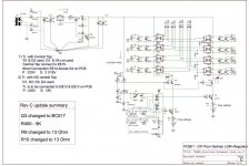
The revised VCCS design removes the current source buffer transistors and places the LEDs in the feedback loop of the opamps that are controlling the current delivery. This reduces temperature dependence of the LED operating characteristics and removes the buffer transistor base/emitter current error. Whilst this does not affect the temperature dependence of the light dependant resistor itself it does reduce other variables in the thermal stability equation.
To clarify what you are suggesting regarding the current source buffer transistors. Please correct me if my assumption is wrong. I am assuming that you are suggesting adding another transistor to any given buffer transistor, connecting the base terminals together, providing an additional current scaling resistor from the additional transistor emitter to the 5 volt shunt regulator and an LDR LED in the collector circuit on the assumption that it would track the buffer transistor already in the feedback loop of the opamp. The temperature dependence of the feedback loop buffer transistor base/emitter junction voltage is compensated by the opamp although the base/emitter current is still an error factor as this is subtracted from the current feeding the LED. The additional transistor would not have the benefit of any loop compensation and may drift significantly enough to upset balance between the various LDRs with temperature change. Also the LDR LEDs operating characteristic temperature dependence is uncompensated in this arrangement.
If you want balanced operation, it would be possible using the revised VCCS design, by increasing the power supply input voltage to around 18 volts and re-scaling the voltage bias chain to centre the opamp operating range. This would allow two opposite phase (as in balanced signal) LEDs to be wired in series within the opamp feedback loops without running out of voltage headroom in the opamp output stage. The buffer transistors would not be needed and there is therefore no base/emitter current error term in the equation. I will develop this option for the application note.
Please feel free to discuss this topic (or any other topic) if I have missed anything relevant in my analysis.
Regards
Paul
MindaLT said:
Thanks for your explanation - that is really helpful.
If I understand correctly for non-balanced setup I only need one Optivol. Also, I hope Optivol also uses matched LDRs as it is supposed to be stereo device? For me attenuated output is not a problem, since I rarely exceed 1/3 of the source output.
Mindaugas
Happy to be helpful ! Anyway, if there is not enough gain with it, you may lower the value of the 27 K, but you'll simultaneously reduce the min value of the attenuation (it will remain louder for max attenuation but who cares...) and then obviously the range too !...
georgehifi said:
As for steped volume control there is no problem in using a 24 or 32 position resistor switched pot for the control for the leds in the Lightspeed Attenuator so long as it mimics a 100k log pot.
As you said even using Tentlabs digital readout volume control as the led controler in the Lightspeed, but ouch that's getting expensive $400aud just to give a digital readout for the Lightspeed.
Cheers George
Hi George,
I have the Jos van Eijndhoven Audio Volume Relay Attenuator. It has 64 steps and very similar to Tenlabs. Well, to what I know they are good friend too. http://jos.vaneijndhoven.net/switchr/design.html
Do you think it can be used as the 100K pot in your light attenuator? A bit over kill but the remote control and digital readout will keep wife happy.
TIA,
Sam
Hi Sam, yes you can use it with the Lightspeed Attenuator as I've designed it, I can't comment on it's operation with the many variations of my Lightspeed design in these pages, it doesn't matter what type of control you use with mine, so long as it's a dual 100K Log (audio taper).
In fact I was looking at this myself as I am the Tentlabs agent here in Australia also, but even at the price I could get it for I couldn't justify the price to just have it as the led's current controler, but if you have one laying idle by all means use it as it is one nice piece of kit and should work every nicely with the Lightspeed Attenuator, and it does look the part. "very wife friendly"
"Maybe Guido will slip me a promo one"????
Did you hear that Guido? Na! he's deaf when it comes to things like that, he's Dutch you see!
Cheers George
georgehifi said:Hi Sam, yes you can use it with the Lightspeed Attenuator as I've designed it. , I can't comment on it's operation with the many variations of my Lightspeed design in these pages, it doesn't matter what type of control you use with mine, so long as it's a dual 100K Log (audio taper).
Cheers George
Sweet! Mine is the 25K, 2006 version. By replacing the 24 resistors, it can be be 100K.
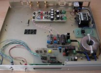
Here's my first go with those LDRs. My thanks to George for making me discover this component and to Barry who pointed out the use of an AD420 DAC as current source.
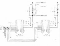
I'm using a 16F628 PIC wich has control over an infra-red receiver, two push buttons, two AD420 DACs, an LCD display and some I/O ports to drive relays. I recently found some mercury wetted models in an old stock at work and will test them in this project. The attenuator is an R-LDR one, followed by a complementary JFET buffer (K170/J74). I run two LDRs in // to keep the serial resistor as low as 15K. That gives me 57dB of attenuation with an 1dB step wich cover my needs. It was a pain to set given the temperature behaviour of those LDRs.
I'm happy because the whole thing is now working very well. Dead quiet at idle whatever the setting, neutral and well detailed during my first listening. It's better than my PGA2311 pre, more airy is the first thing that comes to mind.
The program has some weaknesses like no self learning of the remote control codes, no 'in situ' setting for the dac words of the lookup table given the lack of eeprom data memory in the PIC I choosed. Next step should be an LDR-LDR attenuator.
But usually, when something I build perform so good, I become somewhat lazzy...
Francis
Attachments
- Home
- Source & Line
- Analog Line Level
- Lightspeed Attenuator a new passive preamp