I completed the measurements on the first set of 10 units. These are in series so they all share the same current:


What I noticed is that at 14.8mA I get 21-26 Ohms. I think I have a good match on the first 8 units. I will look into the statistics on these 8 units to see how good the match is.
What I noticed is that at 14.8mA I get 21-26 Ohms. I think I have a good match on the first 8 units. I will look into the statistics on these 8 units to see how good the match is.
If you ask me, you're making a mountain out of a mole hill, simply all you have to do is match up the impedance of the quad set of NSL's at 3 x mA points 2.5mA 10mA 20mA and then calibrate out any differences and the end with the 1kohm trim pot on the loudest channel, or if you want them even more matched so that maybe you can omit the trim pot then match up the impedances at 5 x points, say 1mA 5mA 10mA 15mA and 20mA
Cheers George
Cheers George
Hi George.
thx for the advise. I found the first 4 that have a good match (within 5%). I will build in the 1kOhm trim pot for final adjustment with a signal generator and scope.
Some questions:
I am really looking forward to the hearing this volume control.
regards and thx again for any help
thx for the advise. I found the first 4 that have a good match (within 5%). I will build in the 1kOhm trim pot for final adjustment with a signal generator and scope.
Some questions:
- I noticed that I already get below 25Ohm at 14.8mA. Is this also what you get?
- Is there a limit on the wattage of the 100k log pot? I almost ordered a 16mm pot but after reading most of the threads I switched to a 24mm 0.25w pot from Blore Edwards in the UK. It is difficult to find a 100k log pot with a 30mm or longer shaft. I will be using a dual gang pot
I am really looking forward to the hearing this volume control.
regards and thx again for any help
It will be different with all quad sets, remember your doing series/shunt, if you don't and only do shunt ldr with fixed series resistor you won't get the range low to high you want. Don't over complicated thing you'll go nutz.I noticed that I already get below 25Ohm at 14.8mA. Is this also what you get?
Cheers George
Ok I have several matched quads. The ordered 100k dual gang log pot is delivered along with some 0.1% 100R resistors. I am looking at the power supply. The amp that will received the volume control has a rectified 7V voltage for front panel leds. I intend to use a LT3045 regulated supply to convert the 7V into super regulated 5V for the LDR's. I can get a 0.5A and 1A lt3045 regulator. Would 0.5A be sufficient?
regards
Harold
regards
Harold
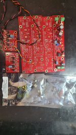
I milled a proto pcb to replace a pot in an integrated amp. I populated the pcb with the first quad of matched ldr’s. This is how it looks like:


the ldr’s are not yet soldered in but just inserted into the sockets.
In this setup I can tune both channels with a trimpot ( I know one pot should be sufficient). I use a 1khz 1v sine wave on the input of both channels and only very minor adjustment was needed. This is how the channel match is now:

This is still powered by a lab psu . Next step are:
1) to put it in the amp
2) work on the 5v power supply in the amp
3) perform measurements and first listening tests
4) thermal coupling of the ldr’s and soldereing the ldr’s to the sockets
The pcb also accepts caps over the led’s but that is for later.
the ldr’s are not yet soldered in but just inserted into the sockets.
In this setup I can tune both channels with a trimpot ( I know one pot should be sufficient). I use a 1khz 1v sine wave on the input of both channels and only very minor adjustment was needed. This is how the channel match is now:
This is still powered by a lab psu . Next step are:
1) to put it in the amp
2) work on the 5v power supply in the amp
3) perform measurements and first listening tests
4) thermal coupling of the ldr’s and soldereing the ldr’s to the sockets
The pcb also accepts caps over the led’s but that is for later.
I have it running now in the amp and what can I say. I never expected this increase in sound quality. I am already very happy with as it is now. Still running on the lab psu. I am waiting for the lt3045 5V board now. I also designed a 3D printed housing for the the LDR's to pot them.
keep you posted
keep you posted
So I made some updates. The LDR volume is now running from a Salas L-adapter external PSU that I have for powering a DAC. Totally overkill but I wanted to hear the difference to the LAB PSU. I also had some Oscon 220uF 16V polymer caps that I put over the LED of each LDR. What can I say. I do not know to describe this but this is a real jump from the ALPS RK40 in the amp. I never heard the amp like this before. The Sansui AUX1 has a buffer (Flat amp) after the volume pot that can be switched of and on, so that is nice if the source is not compatible with the LDR.
At one of our audio society meetings, I have A/B with a few listeners, pure battery power v this linear plug pack, and while some said there was something they thought they could detect, they also said it was so minute and could not reliably pick it in a blind A/B comparison.The LDR volume is now running from a Salas L-adapter external PSU that I have for powering a DAC. Totally overkill but I wanted to hear the difference to the LAB PSU.
Cheers George
Attachments
Hello folks,
The Lightspeed Attenuator journey continues !
Sourcing reliable, quality parts in our crazy world is certainly interesting….
At least at first, we’ll be offering the standard models ie The Single Level Control along with the Dual Level Control as an option.
Most importantly, if you have any ideas, constructive criticism, opinions or tips, please don’t hesitate to let me know.
Lastly, a new website is coming where you’ll find everything Lightspeed related in one place, with a clear & straightforward layout.
Cheers
Scott
Hello everyone!
I bought 2 kits from Uriah 10 yers ago! First one no problem, the latter began to fail at the end of 2021, being in use from 2016. 250k dual pot to have an average of 20k input impedance, schematics as George suggests. Sometimes a channel goes full loud, i thought it was the pot so i changed but no solution and it does strange things. Maybe one or more ldrs are gone...
Udailey or others, do you sell kits nowadays? I don't want to come back to standard volume pots, please help!
Cheers,
Giovanni
Last edited:
Have 2 kits almost not used at all laying in the basement. I am sure they also are 10 years old ")
Easter holliday now but will check into it and take a couple of pics when I get home..
Also have a couple of "lighter note" pcbs (and components) still in its package.
Easter holliday now but will check into it and take a couple of pics when I get home..
Also have a couple of "lighter note" pcbs (and components) still in its package.
Many thanks and happy Easter! I will contact you after holidays.Have 2 kits almost not used at all laying in the basement. I am sure they also are 10 years old
Easter holliday now but will check into it and take a couple of pics when I get home..
Also have a couple of "lighter note" pcbs (and components) still in its package.
I have optimized the design and build it into an integrated amp. Very happy sofar with the results.
What I did.
Next step is to finish the internal PSU with or without filter and mill a PCB for the volume pot that also contains the adjustments pots.
Another question:
I am also considering this volume control solution for a tube amp that I am working on. Originally i intended to replace the old pot's with a stepped attenuator.
The orginal amp has the following setup:
This is the shematic for tube amp

It looks to me that there are several section in the pre-amp with intermediate tube buffers.
Would it be possible to use the LDR in this circuit? I think the balance pot could still be used replacing the two adjustment pots for the left and right channel. I do not want to go to a pot for the left and right channel.
Could the power amp have another LDR?
regards
Harold
What I did.
- first matched some LDR's. I have a batch of 30 and found several quad matches within 3%.
- I built a proto by CNC milling a pcb and connected that into the amp with an external PSU (Salas L-adapter). Based this on George's design but added some OScons i had.
- Next I switched to the 7V PSU (that was available in the amp) to power the volume control. I added a LT3045 regulator to bring the 7V down to 5V. SQ same as with L-adapter
- I design a 3D printed housing for the LDR's so i can assemble 4 LDR's in a tight fit with some heatsink paste between the LDR's to couple them. I also milled a new PCB. This PCB is glued to the 3D printed housing and closes the housing on the top side. This PCB contains 4 100UF Oscons, 4 Murata 470nF SMD caps and the 4 100R resistors. Everything within a 31x23mm PCB. PSU is still the LT3045 but I am testing this with an LCR filter. Adding the SMD caps really was a next step in SQ but i am not sure yet if the LCR filter has any influence and If it contributes anything since I am using a linear power supply as source,
- With the new PCB the LDR legs are directly soldered to the PCB where normsally the wires from the original pot go (to have the shortest signal path).
Next step is to finish the internal PSU with or without filter and mill a PCB for the volume pot that also contains the adjustments pots.
Another question:
I am also considering this volume control solution for a tube amp that I am working on. Originally i intended to replace the old pot's with a stepped attenuator.
The orginal amp has the following setup:
- a 250kB (linear) volume control pot with a log resistor of 33K and a loudness circuit
- coupled to a 500kMN balance pot
- a 250kA log pot in the input of the power amp
This is the shematic for tube amp
It looks to me that there are several section in the pre-amp with intermediate tube buffers.
Would it be possible to use the LDR in this circuit? I think the balance pot could still be used replacing the two adjustment pots for the left and right channel. I do not want to go to a pot for the left and right channel.
Could the power amp have another LDR?
regards
Harold
Last edited:
Witam serdecznie.
Mam zbudowany przedwzmacniacz pasywny wedlug Pana Georga LDR MKII,gra wysmienicie.
Mam pytanie ,czy moge podlaczyc do niego, wzmacniacze mocy jako Bi-amping?.
Impedencja wejsciowa wzmacniaczy 100kOhm.Pytanie czy bedzie dalej zgodnosc impedencji w tym polaczeniu.
Pozdrawiam
Mam zbudowany przedwzmacniacz pasywny wedlug Pana Georga LDR MKII,gra wysmienicie.
Mam pytanie ,czy moge podlaczyc do niego, wzmacniacze mocy jako Bi-amping?.
Impedencja wejsciowa wzmacniaczy 100kOhm.Pytanie czy bedzie dalej zgodnosc impedencji w tym polaczeniu.
Pozdrawiam
- Home
- Source & Line
- Analog Line Level
- Lightspeed Attenuator a new passive preamp