Pete I just asked Peter Daniel to comment he knows his amps better than I do, but to me it may not be possible as the LM3875 has a biopolar input and you can only go so high before they start to loose the plot,
But there is a work around because you have the Lightspeed hooked up this maybe ok to run it with say a 100k on the input instead of 20k, but never turn it on without the Lightspeed attached as this gives a 7k ref to ground then for the input bipolars of the LM3875. It maybe ok to run it like this, but a bit deadly if switched on without the Lighspeed attached.
Cheers George
George, thanks for the advice, i did not realise this. Please post any advice/info that you recieve from Peter Daniels as apart from me there may be other Gainclone users interested in using a Lightspeed.
Cheers
Pete
Hi all,
I have been lurking here for a while with the intent of using these LDRs at some stage - in the meantime let me contribute with this link for the audio characteristics of these devices : http://www1.silonex.com/audiohm/constants.html
John
I have been lurking here for a while with the intent of using these LDRs at some stage - in the meantime let me contribute with this link for the audio characteristics of these devices : http://www1.silonex.com/audiohm/constants.html
John
Pete, this is what Pete Daniel sent me on the LM3875.
Quote>Hi,
I'm using minimized configuration with 22k feedback resistor. The input
impedance will influence the DC offset. Anything higher than 22k is not
recommended as the offset increases. With 50k you may get 200mV or so,
depending on chip.
The input shunt resistor in my amps (kits) is 22k so it takes care if you
use higher value potentiometer. 50k is still fine, as the combined shunt
impedance will never be higher than 22k.
Peter< Quote
So from that I say you can change the input resistor to say 200k but always have the Lightspeed attached and powered, before turning the amps on, this should keep the dc offset low.
Also I would keep the interconects to a minimum length with good sheilding.
Then I would work on getting the ouput impedence of your source (CD player) down to below 50ohms with a good strong opamp 50mA or so (I like the AD825 for this).
Cheers George
Now that I have dipped my toes in this thread, can I ask for a kind of roundup of the preamp - I have read through most of the thread a while ago but have forgotten the salient points.
By way of a summary could somebody provide answers to the following
1. What is the latest schematic which is the least critical of matching
2. How many 32SR2s should be ordered to build a (matched) stereo vol control
3. I can get 32SR2 here for €2.69 each - seems a reasonable price?
4. Has there been a group buy in UK yet?
Thanks
John
georgehifi said:
Or eek! use opamp buffers.
Has anyone tried this yet? I know it violates the Zen simplicity of this design (which I appreciate) but it sounds like an interesting idea for dealing with some of the system mismatches... Maybe a BUF634?
blip1882 said:
Has anyone tried this yet? I know it violates the Zen simplicity of this design (which I appreciate) but it sounds like an interesting idea for dealing with some of the system mismatches... Maybe a BUF634?
I've tried the Lightspeed with many different solid state, opamp, and tube buffers, and this tube buffer one was the most transparent of all, 200ohm ouput impedence, but it was still easily beaten by the Lightspeed by itself with no buffer, so long as cd was low and strong and input of the amp was high.
Cheers George
Attachments
georgehifi said:
I've tried the Lightspeed with many different solid state, opamp, and tube buffers, and this tube buffer one was the most transparent of all, 200ohm ouput impedence, but it was still easily beaten by the Lightspeed by itself with no buffer, so long as cd was low and strong and input of the amp was high.
Cheers George
Hi George,
Care to share more details on the parts? That's a JLTi front end for sure. Hopefully Joe Rasmussen does not mind. Buy hey, we're here to DIY. Look how generous Mr.Pass is
")
Will said:
Hi George,
Care to share more details on the parts? That's a JLTi front end for sure. Hopefully Joe Rasmussen does not mind. Buy hey, we're here to DIY. Look how generous Mr.Pass is
Cause he won't mind it was posted on his web site, I've asked Allen Wright (I think it's his design) to answer you, to fill in the values as I won't even though I know, it's not ethical, it's up to him now to respond. Here is the page in full that was posted.
Cheers George
Attachments
SEA-SAW circuit for mismatched LDRs
Thanks George...I cannot hear scratching pots anymore in future
I read the thread just few days back when it was over 40 pages.
The first thing I did was that I bought a dozen of LDRs and lots of LEDs and experiment. LDRs are very cheap here but are like distant cousins(no similarity)
The first 4 LDRs surprised me. They had so much of a mismatch. One showed around 400 ohms in front of a lighted LED and the second showed around 800 ohms infront of the same LED.
I first injected 18mA into the seasaw circuit and discontinued as priority was to listen to them in my amp and not design the sea saw current drive as it would be time consuming.
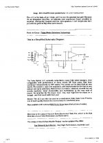
The main aim was to use locally available totally mismatching LDRs. Then I went for the voltage drive, and came up with the circuit attached.
The circuit without the mismatch adjusting preset showed about 11 Kohms with pot in one side and over 30 Kohms on the other.
The mismatch adjusting preset value I used was 1 Meg but this will go bigger if the LDRs are better matched, and will be used in the branch of the higher value LDR(When its LED is dim).
This circuit will take away the time consuming, frustrating hassle of matching the two devices.
I forgot to mention I made my own optocouplers with LED and LDR.
If anybody is interested, then I will post the construcion details.
Enjoy
Gajanan Phadte
Thanks George...I cannot hear scratching pots anymore in future
I read the thread just few days back when it was over 40 pages.
The first thing I did was that I bought a dozen of LDRs and lots of LEDs and experiment. LDRs are very cheap here but are like distant cousins(no similarity)
The first 4 LDRs surprised me. They had so much of a mismatch. One showed around 400 ohms in front of a lighted LED and the second showed around 800 ohms infront of the same LED.
I first injected 18mA into the seasaw circuit and discontinued as priority was to listen to them in my amp and not design the sea saw current drive as it would be time consuming.
The main aim was to use locally available totally mismatching LDRs. Then I went for the voltage drive, and came up with the circuit attached.
The circuit without the mismatch adjusting preset showed about 11 Kohms with pot in one side and over 30 Kohms on the other.
The mismatch adjusting preset value I used was 1 Meg but this will go bigger if the LDRs are better matched, and will be used in the branch of the higher value LDR(When its LED is dim).
This circuit will take away the time consuming, frustrating hassle of matching the two devices.
I forgot to mention I made my own optocouplers with LED and LDR.
If anybody is interested, then I will post the construcion details.
Enjoy
Gajanan Phadte
Attachments
Hey Gajanan,
This is just what I'm looking for - a circuit that allows me to use unmatched LDRs.
I don't follow the schematic - where is the input & output? Could you redraw for the Silonex NSL optocouplers?
Thanks for posting here & yes I would be interested to hear about your construction of the optocouplers
John
Will said:
Hi George,
Care to share more details on the parts? That's a JLTi front end for sure. Hopefully Joe Rasmussen does not mind. Buy hey, we're here to DIY. Look how generous Mr.Pass is
Will Allen has replied, and this is what he (edited) said, I, get onto the moderator and see if I can sort it out.
Quote> George,
i would be happy to contribute to this thread but the ------- STUPID forum won't allow me to look at or post anything.
I don't remeber the password I joined with, and when I request:
1/ a password reminder I am told my email is invalid
2/ or when I try to join newly, I'm told I'm already a member - so go back
to problem #1
Just flat out STUPID!
And I can't find anyway to reach a moderator etc
Allen <Quote
Cheers George
georgehifi said:
Will Allen has replied, and this is what he (edited) said, I, get onto the moderator and see if I can sort it out.
Quote> George,
i would be happy to contribute to this thread but the ------- STUPID forum won't allow me to look at or post anything.
I don't remeber the password I joined with, and when I request:
1/ a password reminder I am told my email is invalid
2/ or when I try to join newly, I'm told I'm already a member - so go back
to problem #1
Just flat out STUPID!
And I can't find anyway to reach a moderator etc
Allen <Quote
Cheers George
This is so sad, to read such a response from a well respected audio designer. These are simple obstacles that a non IT savvy person could overcome.

Matching
Gajanan,
I think you still might need to match the otoisolators up. When I matched some up, the relationship between current and resistance is non-linear.
Trying to plot them, the x axis offset and slope of the line vary. This was found using a batch of sorted diodes.
I can see where your circuit will handle thye offset value. The slope may not get fixed. Maybe I am missing this.
Matching is not that difficult. Use a fixed voltage source, so five volts. Figure 1.5 volts across the led. Then try figure the resistor needed for 2.0 ma, 0.5 ma, and 0.1 ma. Measure the resistance at the three levels. Either plot this or just look at the trends.
I would not worry too much about exact matches. Once I measured dual pots and saw poorly they tracked this is not critical.
Most dual audio taper pots measure +/- 10% end to end, The tracking during rotation is much worse. I have seen some that are off by 50% at 25, 50, and 75 percent rotation. Some of these poorly tracking pots were pulled from my equipment. The poor tracking was barely audible do to how our ears respond to loudness.
George
gmphadte said:JKENY,
Here it is.
Gajanan phadte
Gajanan,
I think you still might need to match the otoisolators up. When I matched some up, the relationship between current and resistance is non-linear.
Trying to plot them, the x axis offset and slope of the line vary. This was found using a batch of sorted diodes.
I can see where your circuit will handle thye offset value. The slope may not get fixed. Maybe I am missing this.
Matching is not that difficult. Use a fixed voltage source, so five volts. Figure 1.5 volts across the led. Then try figure the resistor needed for 2.0 ma, 0.5 ma, and 0.1 ma. Measure the resistance at the three levels. Either plot this or just look at the trends.
I would not worry too much about exact matches. Once I measured dual pots and saw poorly they tracked this is not critical.
Most dual audio taper pots measure +/- 10% end to end, The tracking during rotation is much worse. I have seen some that are off by 50% at 25, 50, and 75 percent rotation. Some of these poorly tracking pots were pulled from my equipment. The poor tracking was barely audible do to how our ears respond to loudness.
George
Thanks Gajanan,
Can you say somehing about how these three pots are used to balance the system. Just to put some figures on these Rs - the two Rs just before pins 1 are 100ohm?. What value for the three pots?
Hi Panelhead,
Are you saying you tried this circuit and found that the mismatch along the slope caused a problem?
My hope was to buy just 4 of these (R2 matched) devices without regard for how close the matching was and use them instead of having to buy excess number (10 or 20) for matching purposes. What are people doing with their unmatched/unwanted leftovers? Surely this is financially & physically wasteful unless some other use can be found for them.
John
excess
Unusable LRD's are why they are not used more. If you read Georgehifi's posts, he uses 100's to get good matches.
I purchased 30 and got good matches for 3 sets of 4. I guess it is possible to match up with less.
To make a normal unit, you only need two matched pairs. The series and shunt elements need to track from channel to channel. But the series and shunt in each channel do not need to be so closely matched.
My best guess would be to get at least 8 sorted LDR's and this should yield two pairs. Might get a quad, but that would be luck.
The four unmatched most likely would work fine. You could use a pair of pots to make a dual mono control. This way any mistracking could be dialed out.
Another advantage of matched LRD's is that the impedance is real close from channel to channel. My R3 diodes give about 25K input impedance with a 100k pot feeding just one channel. In the passive unit I am going to swap to 50K pots to get it down to 10K or so.
George
Thanks Panelhead,
So if I understand you correctly the series LDRs need to be closely matched accross the two channels as do the shunt pair but the shunt pair of LDRs are not critically matched to the series LDRs?
So you reckon that out of 8 (R2 matched) I could get 2 pairs.
What if people posted their measurements for unmatched LDRs here and we could buy matches if they existed accross the matrix of measurements?
Just an idea for getting rid of unuseable LDRs, recouping a bit of lost cash and offering a service to fellow DIYers like myself
John
- Home
- Source & Line
- Analog Line Level
- Lightspeed Attenuator a new passive preamp