Re: Matching for balanced version
Dave, I asume you are letting them warm up a bit before doing the measuring? Also when all is right I pot the 4 ldr's together in hard wax, which keeps things stable. I noticed they do drift a bit after I quickly solder the final selected one in, but this comes back to normal after they cool down within about 5mins. But let me tell you if you give them too much heat I have totaly stuffed them up, and thrown them in the garbage.
Cheers george
David Garretson said:For now I'll retract some of what I posted concerning the difficultly of closely matching LDRs. Remeasuring today some of the pieces I tested yesterday, I'm seeing 10% differences that must be caused by temperature fluctuations in the house during winter! I'm working in a room where ambient fluctuates 5-10 degrees F with the tube stereo warming up or the house heater coming on. The process has been prolonged through temperature changes as I've been using 10 fixed resistors at values between 500R and 1M.
Dave, I asume you are letting them warm up a bit before doing the measuring? Also when all is right I pot the 4 ldr's together in hard wax, which keeps things stable. I noticed they do drift a bit after I quickly solder the final selected one in, but this comes back to normal after they cool down within about 5mins. But let me tell you if you give them too much heat I have totaly stuffed them up, and thrown them in the garbage.
Cheers george
Re: Matching
This is the horrible thing about matching them, I wait about 5 mins before giving each one a rating at the 3 measuring points 9 12 and 3 o'clock on the volume control, are you using dil socketts for the measuring process as this makes it bearable.
Cheers George
David Garretson said:George,
When measuring them I have been powering them up at room tempurature and observing that the resistive value tends to settle down after about 30 seconds. Should I wait longer for them to fully warm up under power?
Dave
This is the horrible thing about matching them, I wait about 5 mins before giving each one a rating at the 3 measuring points 9 12 and 3 o'clock on the volume control, are you using dil socketts for the measuring process as this makes it bearable.
Cheers George
Looks like a VTL3A47, see pic
found these specs for it
Manufacturer = EG&G Inc
Description = Light-Dependent-Resistor-Output Optocoupler
Manufacturer = EG&G Inc
Number of Input Channels = 1
Number of Output Channels = 1
Input Type = Incandesct
Photocell Type = LDR
P(D) Max.(W) Power Dissipation = 550m
V(BR)Out Min.(V)Breakdown Volt = 100
I(IN) Min.(A)Control In. Curr. = 40m
V(IN) Min.(V)Control In. Volt. = 12
r(on) Max.(ohms) On-state Res. = 40
t(off) Max. (s) Turn-off Time = 900m
t(r) Max. (s) Rise Time = 25m
Viso Max.(V) Isolation Voltage = 1.5k
Package = Axial
There is a heap of Melos details at head-fi.org including a service manual of sorts. some of the modded units are using a switched att?
Regards
James
Attachments
tvi said:Looks like a VTL3A47, see pic
found these specs for it
Manufacturer = EG&G Inc
Description = Light-Dependent-Resistor-Output Optocoupler
Manufacturer = EG&G Inc
Number of Input Channels = 1
Number of Output Channels = 1
Input Type = Incandesct
Photocell Type = LDR
P(D) Max.(W) Power Dissipation = 550m
V(BR)Out Min.(V)Breakdown Volt = 100
I(IN) Min.(A)Control In. Curr. = 40m
V(IN) Min.(V)Control In. Volt. = 12
r(on) Max.(ohms) On-state Res. = 40
t(off) Max. (s) Turn-off Time = 900m
t(r) Max. (s) Rise Time = 25m
Viso Max.(V) Isolation Voltage = 1.5k
Package = Axial
There is a heap of Melos details at head-fi.org including a service manual of sorts. some of the modded units are using a switched att?
Regards
James
Good work James
They have 2 in that series, looks good, it's on resistance is low at 40ohm and 60ohm but I can't seem to find what it's off resistance is, because if this is higher than the Silonex
NSL-32SR2S at a max of 5megohm it will be even harder to match up, James did you find out what the off resistance is?
They are cheap enough at $1.50 at this place
http://72.14.253.104/search?q=cache...62800629655+VTL3A47&hl=en&ct=clnk&cd=15&gl=au
In the Melos unit that I saw a pic of years ago, it was a brass tube about 3/8" in diameter but is was all mounted under the circuit board, as if they were trying to hide it from prying eyes and it was the SHA-GOLD REFERENCE but it was a two box unit with the power supply for everything in another box
Cheers George
georgehifi said:
The only thing is you have your 5vdc coming in on the wiper and one end of the resistance track on each section, where I only had it coming in on one end of the resistance track of each section and not the wiper as well. and you'll only need the 1k trimmer on the channel with the highest gain.
Cheers George (Nice drawing BTW).
Hi George...it is actually wired the same because in your case each end terminal of the dual pot where you connected 5Vdc is also wired (short) to the wiper terminal...much like the single pot where it just goes into the wiper.
I think a log pot will adjust volume at a much smoother rate like you said.
Allan
Not LED
tvi said:Looks like a VTL3A47, see pic
found these specs for it
Manufacturer = EG&G Inc
Description = Light-Dependent-Resistor-Output Optocoupler
Manufacturer = EG&G Inc
Number of Input Channels = 1
Number of Output Channels = 1
Input Type = Incandesct
Photocell Type = LDR
P(D) Max.(W) Power Dissipation = 550m
V(BR)Out Min.(V)Breakdown Volt = 100
I(IN) Min.(A)Control In. Curr. = 40m
V(IN) Min.(V)Control In. Volt. = 12
r(on) Max.(ohms) On-state Res. = 40
t(off) Max. (s) Turn-off Time = 900m
t(r) Max. (s) Rise Time = 25m
Viso Max.(V) Isolation Voltage = 1.5k
Package = Axial
If I read this right, there is a lightbulb in there and not a LED. Plus it is a 12 volt light. The LED based LDR should be more stable, linear, and reliable. This type of LDR might explain the negative reception from others.
But it is interesting to see what they used at the time. Remember reading about the light based attenuator back when these were first out. That was back in my tubes heydays, but owned a CAT and VTL Ultimate then. Being single at the time MIGHT have had something to do with it.
George
Just found a review on one of the Melos pre's that used the LDR volume it's the lower priced SHA-Gold not the reference for those out there who think Stereophile is an audio bible it will be interesting for you.
http://www.stereophile.com/headphones/796melos/index.html
Cheers George
http://www.stereophile.com/headphones/796melos/index.html
Cheers George
georgehifi said:I just finished reading the review, and hey they talk about the rectifcation of the music signal when passed through a wiper on a potentiometer and switches as well! Well who would of thought it.
Cheers George
There's little doubt in my mind rectification occurs, Bear's megadoubts aside. Put it this way, if switches are good for sound, why not add hundreds?
You know what the most stupid thing is about this review,
They said Melos (Mark Porzilli) put a 100K resistor in series with the ldr, so in turn the tube buffer stage had to be 10meg ohm input impedence, fair enough the ldr volume control has an output impedence of over 100K and is feeding into a 10meg ohm tube output buffer.
Then they go on to say that the preamp was the most transparent preamp they have ever heard especially when it was used in passive mode, (without the buffer), but they said the bass dynamics suffered just a little this way.
Hell no wonder the bass dynamic suffered a little, they were using a lrd volume control similar to the Lightspeed, but one that had over 100k output impedence, and guess what poweramp it was trying to drive into, a Krell KSA 300 which has (wait for it) only 47k input impedence. No bloody wonder it lost a little bass drive. The Krell should of theoretically have had an input impedence the same as the tube buffer, 10meg ohm. Idiots
Cheers George
Like this?
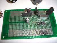
Recently built another board. This a top view, the reg is a LM317HVHP, the output is adjustable via the pot. A Vishay 1280G.
Lostcause said:Hey guy's,
Would it be a bad/good idea to put the 5V regulation and filtering on the same board? I'm pretty tight for space and this would help.
Cheers
Lee
Recently built another board. This a top view, the reg is a LM317HVHP, the output is adjustable via the pot. A Vishay 1280G.
Attachments
Nother idea
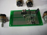
The idea of using one pot to control voltage really got me going. So picked up some single pots with a switch. This way I can turn off the LDR's when not listening. This way they should last close to forever.
So this weekend, in goes the new pots and the choke to filter noise from the 3 pin regs. It is only getting better and better.
George
Attachments
George (Houston), nice Vishay pot there. Lowest noise on the planet no doubt. By the way, I deal all the time with Texas Components, in your neighbourhood.
George (Auz), most reviewers, IME, while perhaps having keen ears, know only enough electronics to say electricity comes from a wall, hence naturally have difficulty guessing which electronic feature might be responsible for what audio result. A progress killer, in some respects.
George (Auz), most reviewers, IME, while perhaps having keen ears, know only enough electronics to say electricity comes from a wall, hence naturally have difficulty guessing which electronic feature might be responsible for what audio result. A progress killer, in some respects.
Re: Like this?
Thanks for the reply Tom
Although I can't seem to get these LDR's matched up The batch I got from Allied had a mix of ranges that go from A to E and trying to get 4 that are close enough is a nightmare.
Why do they not send all the same range? Seems silly to sort them and then mix them all back up again!
Ah well
Panelhead said:
Recently built another board. This a top view, the reg is a LM317HVHP, the output is adjustable via the pot. A Vishay 1280G.
Thanks for the reply Tom
Although I can't seem to get these LDR's matched up
The batch I got from Allied had a mix of ranges that go from A to E and trying to get 4 that are close enough is a nightmare.Why do they not send all the same range? Seems silly to sort them and then mix them all back up again!
Ah well
Lostcause said:Sorry...that should be thanks Panelhead!
When they are matched they should be all the same letter, I would email and complain that they sent non matched, this happened to me once and I kicked up a storm, eventually I went direct to Silonex with my complaint and they fixed it up.
Cheers George
georgehifi said:
When they are matched they should be all the same letter, I would email and complain that they sent non matched, this happened to me once and I kicked up a storm, eventually I went direct to Silonex with my complaint and they fixed it up.
Cheers George
I already complained but they just quoted the spec sheet and said they couldn't help! They did offer me 10% off my next order though...LIKE I'LL BE ORDERING FROM THEM AGAIN!!
Always read the small print!
Attachments
Got a question George. I just installed a pair of output transformers between the LDR output and connector outs. This allowed facilitating a phase switch while utilizing single ended connectors. It scrubbed a bit of volume output but I have gobs. I have attached a data sheet on the transformers. Sound seems very good so I hope there are no bandwidth or other concerns you might have.
http://www.lundahl.se/pdfs/datash/1676.pdf
http://www.lundahl.se/pdfs/datash/1676.pdf
- Home
- Source & Line
- Analog Line Level
- Lightspeed Attenuator a new passive preamp