Hi
I very occasionally have a balance problem too so I get up and adjust the balance knob and sit back down again - it's excellent !!
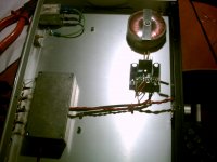
The lightspeed is of course inside the small box - installed after George worried me about temperature fluctuations and the effect on the LDR's
Needless to say, it's still one of the best things I've put in my system.
( Before you say anything....I agree the LM317 based power supply is cr.. but I'm going to do something about it soon )
Andrew
I very occasionally have a balance problem too so I get up and adjust the balance knob and sit back down again - it's excellent !!
The lightspeed is of course inside the small box - installed after George worried me about temperature fluctuations and the effect on the LDR's
Needless to say, it's still one of the best things I've put in my system.
( Before you say anything....I agree the LM317 based power supply is cr.. but I'm going to do something about it soon )
Andrew
Attachments
The box you have the LDRs and (I assume) wax in looks pretty nifty. Maybe I should try that, plus you get some shielding if you ground the box. I have not had a transformer inflicted noise problem in my short memory but people that put the LDRs in DCB1 configurations often seem to have to reposition their transformer to get the noise to go away. Your box would do the trick and allow a smaller enclosure since transformer could be close to the LDRs.
Hi
Needless to say, it's still one of the best things I've put in my system.
( Before you say anything....I agree the LM317 based power supply is cr.. but I'm going to do something about it soon )
Andrew
Andrew hi, I don't know about a LM317 based power supply, but the one that's in the production Lightspeed Attenuator is double regulated, first with a 12v regulated 300-500mA transformer plug pack this is of course external, then this feeds via a 2.1mm plug to the socket on the Lightspeed Attenuator then inside the alloy shielded chassis we have a secondary 5v regulated super smoothed power supply (no transformer), based on National Semi Conductors or TI (Texas Instruments) LM7805.
We have found in listening tests 2 years or so years back with about 40 x "golden ears" at an audio club meeting, that there was no conclusive difference between the standard power supply that comes supplied, when compared on a very high res system directly on the run to pure dc Lithium Ion battery, which was large enough to power 10 x Lightspeeds.
Only a half a dozen "golden ears" thought they could detect something but were not sure, those same "golden ears" have their own Lightspeed Attenuator's and are using the supplied power pack, not battery.
Cheers George
The little box was only installed to add an element of resistance or insulation to heat / cold - of course I also hoped it would maybe add some shielding from it's basic ps and the amps underneath it.
I have not had to touch it in the months I've had it - just the odd tweak to the balance.
George, if I improve the PS further ( a proper one ) can I really expect anything in the way of seriously noticeable sonic gains...like...wow.. sort of improvements ?
I don't mind either way - I'm a very satisfied user already, period
Andrew
I don't know how a LM317 based one sounds Andrew, but if you do one as I've outlined double regualted with a LM7805 as the final regulator, this cannot be improved upon in this circuit, even with battery, and lets face it LI battery is about the best you can get, it even beats liquid cell batteries as they have been said to have bubble noise.
Cheers George
Cheers George
it even beats liquid cell batteries as they have been said to have bubble noise.
Cheers George
I thought bubble noise occurred when a battery was being charged, not discharged...
Battery supplies are not the end all be all to sonics with LDRs. There are many who have posted here in the last year or so that have tried snubbing the LDRs and have had improvements while using regulators. Also, current source is an improvement. Just a while ago one of the members on this thread mentioned that he used batteries and even putting a cap across the batteries made an improvement. Batteries dont do all they are expected to do with LDRs, however they are a good solution and an easy solution. There are better though.
Batteries have extremely low noise, but their impedance is usually in the high hundreds of milliOhms to Ohms.
Agreed Jack, I believe from all the experiments we've done, a battery is the cleanest power source one can do for this application, as we've proved at the shootout batteries were indistinguishable from the standard production Lightspeed power supply.
As far as batteries having a bit of series impedance, it's not an issue here, we've got the series 100ohm resistors and the the 100kohm pot anyway, were not trying to power poweramps or anything that needs to dump high amounts of current, just an led, and you can still put bypass caps across the them with battery, but you are wasting money and a cap.
Cheers George
I agree the LM317 based power supply is cr.. but I'm going to do something about it soon )
An LM317 based regulator is one of the best you can find for 3-leg types. Maybe yours needs some further tuning.
Look here:
http://www.diyaudio.com/forums/powe...ing-lm3x7-regulator-circuit-4.html#post356154
And here:
Simple Voltage Regulators Part 2: Output Impedance
Here I think you should worry more about noise, so a CRC before the regulator might do wonders.
I do believe a battery can be equaled by a proper regulator or even beaten, like in impedance. Depending on the battery it may even have high frequency noise due to chemistry activity.
Carlos
Here a reaction on the discussions a bit above. I made an automatic calibration circuit around the sylonex optocouplers, see the thread here: "182294-sylonex-arduino-preamp". It's working really well. Only limited matching of the optocouplers is needed. And it takes a push of a button and some minutes to recalibrate completely. But only the 1st calibration is really important, later ones don't make huge differences.
I calibrate each optocoupler individually, as this will allow me to control input impedance as well. The result is really OK, but taking into account a lot of small things in the software, mainly due to the slow reaction of the optocouplers at high current.
But before you take a look: I know the circuit is complex. I know it's more expensive then matching the optocouplers etc etc. But it was fun to make, and I can keep on modifying things which is part of the fun.
The final result is great. It will not sound any better then Georges version, but it sounds really good. If you want more info, better ask on the separate thread to avoid spoiling this one.
Okay,
Was contemplating this and now am sure I am going to do it. I am going to offer you guys a board/circuit to match your own LDRs so you can build as many Lightspeeds as you want. This way instead of paying me a matching fee you can buy 20 or so LDRs with your money plus the kit and for the rest of your life have the ability to match LDRs for your project/s.
It will be able to match 10 or 20 at a time. Will have a spot for your DMM to connect to and a momentary switch for each LDR. This way you plug them all in to their on board connectors and wait for them to warm up. Then attach your DMM to the clip-ons and hit a momentary switch for each LDR. Your DMM will tell you the resistance of each LDR as momentary switch is engaged and voila you have matched LDRs for you and maybe even your good buddy who you are kind enough to share your LDRs with")
Mid August
Uriah
Was contemplating this and now am sure I am going to do it. I am going to offer you guys a board/circuit to match your own LDRs so you can build as many Lightspeeds as you want. This way instead of paying me a matching fee you can buy 20 or so LDRs with your money plus the kit and for the rest of your life have the ability to match LDRs for your project/s.
It will be able to match 10 or 20 at a time. Will have a spot for your DMM to connect to and a momentary switch for each LDR. This way you plug them all in to their on board connectors and wait for them to warm up. Then attach your DMM to the clip-ons and hit a momentary switch for each LDR. Your DMM will tell you the resistance of each LDR as momentary switch is engaged and voila you have matched LDRs for you and maybe even your good buddy who you are kind enough to share your LDRs with
Mid August
Uriah
Thanks Jon
I bet you are lol. I will still get you that other board I talked privately with you about. I think I just want to review it in my head a bit further first.
Test setup
I like LM334 and they are cheap. Board will have several of those on board with trimmers on each of them to set current and I think I will do a current sense resistor so you can test at exactly the same current again if you like. I have not used that ever in testing in the past but it sounds like a good idea right now. So you may actually come back tomorrow and test, as long as it's in same temperature, at exactly the same current output. Maybe a big zener before the current sources to set voltage and a 9V as a supply. No, I dont think batteries are the best for an LDR attenuator but certainly a fine solution for a test board. I could put a led string after the zener to ground with a 10k or so series resistor to the LEDs so that once it falls below the zener voltage the LEDs will dim significantly and then shut off. Well, maybe better to give the string their own zener 1Volt higher than the current source' zener so we dont go testing LDRs at to low voltages. Small on/off switch of course.
Probably any more complex than that is getting silly.
Uriah
An LM317 based regulator is one of the best you can find for 3-leg types. Maybe yours needs some further tuning.
Look here:
http://www.diyaudio.com/forums/powe...ing-lm3x7-regulator-circuit-4.html#post356154
And here:
Simple Voltage Regulators Part 2: Output Impedance
Here I think you should worry more about noise, so a CRC before the regulator might do wonders.
Carlos
Carl - thanks for the comments and links - interesting reading.
The LM317 power supply works very well as it is - there is no noise per se,
it's reliable and my lightspeed is a delight to use.
I am however aware from other posts that are better ways of powering it which could potentially bring some gains.
The links you sent provide some food for thought - much appreciated
Andrew
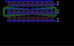
DIY LDR TEST JIG FOR LIGHTSPEED BUILDS
Probably all I will do today.
Its double sided so not all circuitry is obvious but there is not a lot to see either.
You might notice 3 test points. The ALL TP you leave your DMM lead on that one for the whole procedure. The 1-10 the other DMM lead attaches to when testing LDRs 1-10 and obviously switch that same DMM lead over to 11-20 when testing the last 10. This saves a little board space and a bit of cash because we get to use the same momentary switch to test two LDRs rather than just 1.
Imagine 2 resistors in series. To find the value of the first you tie DMM to the middle where they meet and then to the other side of the first resistor and then leave the DMM lead in the middle and move the other to the end of the second resistor to measure it. Same idea here.
Dont worry about the traces being a few inches long. It will make only milliohm differences which we dont care about.
I now have to add power supply circuitry but figured I would give you a look.
Uriah
Attachments
Hi folks,
(Uriah, I've been spamming you directly for support via e-mail, but I think it's better if I just join in on this thread!)
I just finished building one of Uriah's Lightspeed kits, which is very nice indeed. It went very smoothly and I'm really happy with the finished board. My hope is to use it in place of the 50k Alps pot that I currently have in my amplifier.
I measured the resistance of my assembled Lightspeed at min volume with the power on and it's exactly 12.5 kOhm per channel. At half way, it's 4 kOhm and at full volume it's around 150 Ohm. Resistance with power off measures as infinite.
By comparison, the Alps pot that I want to replace goes from roughly 50 kOhm per channel to effectively zero on a 20% log, with some drift towards the end due to its age. I do all of my normal CD listening in the 50-43 kOhm range (7-9 o'clock) and vinyl in the 50-40 kOhm range (7-12 o'clock).
So I think I'd ideally like to quadruple the resistance of my Lightspeed if that's possible. Failing that, I could just add ~37.5 kOhms of resistance in series, but if there's any way to get closer to a 50k log that would be better.
Cheers,
Ben
Last edited:
- Home
- Source & Line
- Analog Line Level
- Lightspeed Attenuator a new passive preamp