woodturner-fran said:Its been a looooonnng time coming, but tonight I soldered up my version of Georges lightspeed.
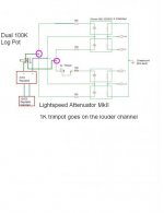
Well, the good news is there was no smoke!!!! The bad news is I think I have the pot laid out backwards. Can someone do a double check for me here.....
That has to be the wrong way around doesn't it?
Damn I double and treble checked that when I was doing the layout!!!
Fran
PS if anyone wants the layout, just email me!!
Good for you, if you have a backwards operation of the volume control just reverse the two conections circled in pink attatched.
Cheers George
Attachments
Many thanks George.
I also need to check that pot - it was a pull from a mixing desk console and its not beyond the realm of possiblity that its some kind of oddball pot.
I have a few of the simple mk1 style lightspeeds in use so first job I think will be to substitute in the mk2 and see how she sounds.
In case I didn;t mention it above, many thanks George for the oppotunity to build this!
Fran
Ok... its me back again for more help!
Got the pot sorted out, reversed it and ran wires back to the board. All works as it should now.
But theres another problem!
I think my DC after rectification is a bit low and the teddyreg is dropping out of regulation. I used schottky diodes and I think they are just dropping too much V. I'll try swapping them out and see how it goes.
Fran
Try it with a "more basic" supply and see if there is any difference in the sound as this just runs the leds - altho the electro caps across the leds do seem to change things a bit.
You may find that just the Cmultiplier section of the TeddyReg with a zener to tie down the voltage will do the job very well indeed - sometimes the simple approach works "better"!
You may find that just the Cmultiplier section of the TeddyReg with a zener to tie down the voltage will do the job very well indeed - sometimes the simple approach works "better"!
Salut
A question for Paul:
I've ordered a set of balanced LDRs for 2 x VCCS (dual stereo - not balanced). However the sorted LDRs need a 500k pot.
I assume the current drive through the VCCS circuit results in an equivalent 100k pot. So the question(s) is/are:
1. Is the need for a 500k pot with Uriah's LDRs relevant to your circuit?
2. If so, how can the circuit be modified?
Thanks Paul.
Vernon
P.S. A question about the 39k resistors either side of the DS1802 - do they as they look just shift the pot range to the middle of an equivalent 120k pot? i.e. a small and largish values could be used to shift the volume variation range to the quiet-end, for example?
Thanks jameshifi,
I will hook up a regular simple supply tonight and see how it goes. Maybe also sub in some other diodes too. I think whats happening is that as the load increases on the teddyreg its dropping out of regulation. So in the middle of pot travel, I'm getting 5V perfect, but at either extreme of pot travel, the voltage is dropping.
Will investigate and report more later. For the record I think the teddyreg needs about 7V headroom and with these diodes it only has 5V. I'm hoping thats the problem!!
Fran
Lightspeed remote control
Hello Vernon,
I believe that a 500K single pot was used for a passive control version of the Lightseed volume control. I do not think that it relevant when using the VCCS.
If you wish to alter the range of action on your VCCS module you can adjust the resistors R1 to R4 (39K to approximate Nelson’s suggested range). R1 and R3 affect the series LDRs and R2 and R4 affect the shunt LDRs. You may find you get a better range match with your system by having different values for the series control resistors to the shunt control resistors. I would suggest you do not use resistor values of less than 330R for a maximum LED current of 18ma. You may need to decrease R10 slightly to allow enough LED drive current but watch the dissipation in T1 [the surface mount BSP149 configured as a current source].
Hi Ray,
I have all the printed circuit boards in stock and will keep them in stock as long as there are requests for them. I can make the modules to order for those who prefer keep assembly simple. There is a lead-time for the modules of up to 15 working days as these are prepared in my spare time. The prices have not changed but if you are ordering more than one PCB check the carriage cost with me prior to ordering as shipping several boards is more economical than shipping one board. I priced carriage for the VCCS and the IR boards separately as the IR boards were introduced later than the VCCS board. When I find some spare time I will update the carriage price list. You can pay via Paypal by sending funds to paul@paulhynesdesign.com but please remember to pay in advance for any currency conversion fees that Paypal charge.
Regards
Paul
Okay guys.
AndrewT suggested that a single gang 1/2W pot might not cut it and could fry. With the circuit the way it is I think max power that could go through the pot is .5W but his argument is that only 7mA is allowed. Something about they are only designed for .25W at higher voltage lower current.
Well, my idea is to then remove all those 100Ohm resistors and put one 680R in series with 5VDC before the pot, not after. The LDRs really dont gain any noticeable resistance til about 1mA anyway so limiting the entire circuit after that resistor to ~7mA doesnt bother me.
Comments?
Uriah
Using two mono pots is fine. I did that with my first one. Its fiddly when you want the stereo image in the center but you do get used to it fast. Still fiddly though.
Each LDR uses up to 20mA then goes ffffftt! Thats what the spec sheet says. I have had customers who poofed theirs and while experimenting I have poofed a few but I have also given plenty of them more than 20mA, however its my opinion that this ends up changing their resistance curve. In general they are operating at under a milliamp. Way way way under.
Uriah
udailey said:
In general they are operating at under a milliamp. Way way way under.
Uriah
A 1/2 watt pot ought to be fine then

Just need to make a supply with very low power
2x6V 0.35AV is the smallest I have seen so far
Dont understand
Does the LDR draw more power than they need to work ?
Might seem like a good idea with 2 step power on switch
Uriah,
I am about to try something odd for the 500K pot - have you seen the GlassWare TCJ Stepped Attenuator? It has three switches, a central one to coursely control the volume with a couple of ladders on each side - this is designed to be a fine volume control - not a balance control, but it can be used that way.
I have bought a set of 1W resistors which I will be putting together soon - I was going to wait for the new B1 Buffers but I may as well give it a go - soon.
Alan,
Thats cool but why not just put another pot in between the original pot and the LDRs? Wire it just to the series LDRs only using half of the new pot. Since we are only doing fine volume control with this pot the overall input impedance of the LDRs should change very little. Use a 10k pot or so. Maybe wire it in with the Shunt resistors to.. Probably makes no difference.
Uriah
Uriah,udailey said:Alan,
Thats cool but why not just put another pot in between the original pot and the LDRs? Wire it just to the series LDRs only using half of the new pot. Since we are only doing fine volume control with this pot the overall input impedance of the LDRs should change very little. Use a 10k pot or so.
Uriah
I was looking for stereo 500K pots and I was a little worried by some of the posts about overloading the pots - this seemed like a good idea since I could use higher power resistors - plus I had been wanting to try one of these for a while.
One small advantage is that the switches are on the outside - which I think is the way you were doing rather than using trimmers.
Alan
If I throw a 680Ohm in front of the main pot it wont overload. I dont think it ever will anyway especially since the minute I turn it up at all the current through either side is under a milliamp.
I am suggesting to use another chassis mount/panel mount pot so you can adjust from the outside of your chassis for the fine volume control. OR use a multiturn 500k pot.
The only reason I mention this rather than your idea is that the pot you are suggesting to use might be expensive. Nice idea though and with how fast these increase in volume it might be a great idea for many people to try.
Uriah
- Home
- Source & Line
- Analog Line Level
- Lightspeed Attenuator a new passive preamp