AlanElsdon said:
For the HT12A try 97K1716, for the HT12D try 24M2761.
ok, I got my parts from Mouser, I am now ordering the IC's from Newark.
I am seeing the parts spec'ed above as SMD components and I "think" the PCB is set up for hole through.
HOLTEK - HT12A 18 DIP -
Manufacturer:
HOLTEK
Newark Part Number:
97K1716
Manufacturer Part No:
HT12A 18 DIP
RoHS Compliance : RoHS Compliant Yes
Description
* Termination Type:SMD <---------------------- HERE
* Package/Case:18-DIP
* No. of Pins:18
http://www.newark.com/jsp/search/productdetail.jsp?sku=97K1716&_requestid=160901
daredevil_kk said:Thanks guys for your feedback.
I will be doing a Lightspeed MkII and a Linkwitz-Riley Crossover from ESP. I was thinking about using the LM4562 with a 100k input impedance. Anyone have any other suggestion?
Oops!!! How do I increase the input impedance to 100k?

There are a lot of Analog Devices opamps that would be great as well, but you have chosen a very fondly looked upon opamp and while I have heard that it is a little bright I think that if you like the Lightspeed you will like the LM4562 as well since the main thing I like about the Lightspeed is its detail and accuracy which with a 'bright' opamp will just be more obvious.
Wow, really long sentence!
Uriah
Wow, really long sentence!
Uriah
daredevil_kk said:
Oops!!! How do I increase the input impedance to 100k?
If the LM4562 is fet input just make the input resistor 100k, if it is not you can still do it but your dc offset may vary or drift if it does then you'll need a coupling cap (dc blocking cap) yuck!
Cheers George
georgehifi said:There's this one too which has output buffer and level controls where you could slot your Lightspeed into instead of the pots.
Cheers George
Yup, the cross over (with output buffer) that I am building is almost the same as the one you shown.
http://sound.westhost.com/project09.htm
It is too complex to use discretes, hence the opamp. I choose
the LM4562 as I think it one of the more accurate sounding one. I will use the TDA1541 dac to "tune" the sound. My only worry is that it will be too bright sounding as I will be using LM4562 for all the opamps in the x-over. I am open to any other opamp suggestions.
From the specs, LM4562 input impedance is 30k for Differential Input Impedance and 1000M for Common Mode Input Impedance (I have no idea what is that)
http://www.national.com/ds/LM/LM4562.pdf
George, what is your suggestion for the value for series and shun resistors before the input buffer.
Thanks

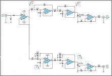
the input and output buffers can be non-inverting, as shown in the post attachment, or as inverting.
In inverting mode one can set up the buffers to gain of 1 (+0db) or as amplifiers with gain>1 (+>0dB) or as attenuators gain<1 (-0dB).
A single J170 or BF862 can be used in the buffer locations.
or go the whole hog and use a B1 buffer at these locations.
Similarly a Jfet can be used in the active filter opamp locations.
A three leg transistor and a couple of resistors is not much more space consuming than a dip.
If you want to use silicon you can also check out the buffer that Nelson Pass posted earlier in this thread for use with the LDRs. It would be an easy build and I agree with Andrew that the B1 would be a good choice. Easy to build as well. Actually nearly on par with building the Lightspeed as far as ease of build.
George has many times posted a tube buffer circuit in this and other threads.
Uriah
George has many times posted a tube buffer circuit in this and other threads.
Uriah
georgehifi said:
f the LM4562 is fet input just make the input resistor 100k, if it is not you can still do it but your dc offset may vary or drift if it does then you'll need a coupling cap (dc blocking cap) yuck!
Cheers George
I don't like coupling caps too... Skipping them all the way and will be using Isolating transformers at the output of the crossover.
Anyway guys thanks for all the suggestions. I finalize to use LM4562HA for the crossover to keep inline with the clean sound of the preamp and use a JFET buffer or the B1 after the TDA1451 to tweak the final sound.
Will keep u guys posted about the outcome.
My Adcoms have a DC servo on them that keeps DC offset incredibly low and they sound pretty good. Not fantastic but a step down from that. They are Class AB and meant to be driven a lot harder than I do so I dont know if the DC servo is doing anything to the sound or not. Might be a very good way to escape using a cap or a transformer.
Uriah
Uriah
transformer
Hello- I am new to this thread, and very interested in building this little guy, but have the same issue with impedance matching that some others have. I've seen Nelson Pass solution to this, which is basically to make it into an active preamp. But the passive solution is so elegant!
I was thinking why not just put an audio transformer at the input, to to the matching. Anyone else have this idea, or tried it?
transformer
the input impedance of my amp is not a problem- 500K.
But my DAC's output is 800 Ohms.
Between the DAC and the Lightspeed, I was thinking about putting a Hammond 850N (Mouser #546-850N). Although that one is pretty expensive. The 546-560N might also work pretty well for about 65$.
Anyone else tried this approach?
transformer
Actually- I am going to have to retract my suggestion. I do not believe that a transformer will be necessary. I think the solution is just to go with the R3 vs the R2S, as Nelson Pass pointed out. It has a much wider range of resistance, and just goes much higher in resistance. I cannot see how the input impedance of the lightspeed attenuator would ever be below 5K, using the R3. Look at the 2 tables of resistance vs. mA of the R2 and R3 Nelson posted on page 54 of this thread.
But if in fact, anyone really needs a much higher input impedance than that, I think the transformer approach would work out rather well. I don't think it would adversely affect the sound.
Its been a looooonnng time coming, but tonight I soldered up my version of Georges lightspeed.
What I've done here is modify the layout slightly so that the board takes AC right from the transformer, rectifies it and then power from that is routed through a teddyreg. This is basically a super regulator giving a clean supply out. The teddy reg is the separate board that "plugs" into the lightspeed board underneath.
Well, the good news is there was no smoke!!!! The bad news is I think I have the pot laid out backwards. Can someone do a double check for me here.....
Pot at minimum, resistance across the series LDR is low (I think I measured 50R or something like that. Turn up the pot and the series resistance increases.
That has to be the wrong way around doesn't it?
Damn I double and treble checked that when I was doing the layout!!!
Fran
PS if anyone wants the layout, just email me!!
An externally hosted image should be here but it was not working when we last tested it.
What I've done here is modify the layout slightly so that the board takes AC right from the transformer, rectifies it and then power from that is routed through a teddyreg. This is basically a super regulator giving a clean supply out. The teddy reg is the separate board that "plugs" into the lightspeed board underneath.
An externally hosted image should be here but it was not working when we last tested it.
Well, the good news is there was no smoke!!!! The bad news is I think I have the pot laid out backwards. Can someone do a double check for me here.....
Pot at minimum, resistance across the series LDR is low (I think I measured 50R or something like that. Turn up the pot and the series resistance increases.
That has to be the wrong way around doesn't it?
Damn I double and treble checked that when I was doing the layout!!!
Fran
PS if anyone wants the layout, just email me!!
An externally hosted image should be here but it was not working when we last tested it.
- and theres an error on this layout that I later fixed, but at least you get the idea.
After the RCAs take signal ground and solder it where you have the signal IN wire then take the signal in wire and solder it where you have the ground wire. See your Series LDR will now be your shunt LDR and when you turn the volume up it will go up rather than down.
Right now at zero volume on your pot you have full volume. Your present series resistor is at low resistance and the shunt is at high. So its loud. Reverse their inputs and you will make your shunt your series and your series your shunt and everything will be fine. OR you could reverse the wiring from the potentiometer and accomplish the same thing.
I love it that you guys are building such a great little pre with the LDRs that I worked on.
I nearly worked myself blind today and completely fried my brain reading LDR measurements on my spreadsheet. But, the result is that I have a great matching batch of LDRs
Uriah
- Home
- Source & Line
- Analog Line Level
- Lightspeed Attenuator a new passive preamp