I have found the numbers for my coils, they are T106-26.
Al is 93. Suitable ? I can make a coil that can withstand 10A, one of the original windings is good for 20A, at 5v tho but at the same time as another winding is 8A and 12v and two more 500mA each, so atleast 5A in 20-30v shouldent be a problem.
fredos, i live in sweden so i think its alittle too mutch money getting your nice coils for a project that will most likely stay as a protoboard item, unless you could help me with layout and board making.
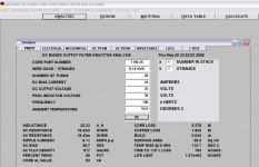
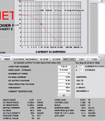
I did some calculations on the cores i have, T106-26:
Al is 93. Suitable ? I can make a coil that can withstand 10A, one of the original windings is good for 20A, at 5v tho but at the same time as another winding is 8A and 12v and two more 500mA each, so atleast 5A in 20-30v shouldent be a problem.
fredos, i live in sweden so i think its alittle too mutch money getting your nice coils for a project that will most likely stay as a protoboard item, unless you could help me with layout and board making.
I did some calculations on the cores i have, T106-26:
Attachments
What cad tool are you using?
As for having the boards made, try Olimex, they only charge 33$ for at double sided euro sized card (100 x 160 mm).
Olimex
Dont think you'll find much better service or cheaper PCBs anywhere")
I have used them 4 times and everything has been perfect.
They don't charge for panelizing, and you can mix different PCBs on the same euro card
As for having the boards made, try Olimex, they only charge 33$ for at double sided euro sized card (100 x 160 mm).
Olimex
Dont think you'll find much better service or cheaper PCBs anywhere
I have used them 4 times and everything has been perfect.
They don't charge for panelizing, and you can mix different PCBs on the same euro card
Another question about filter coils. (hope it's not too much off track for this thread)
In the design I'm working on, I'm using an H-Bridge.
I'm using a coil I had laying around, and have wound both coils on the same core.
With high voltage (56 VDC) the coil got very hot. As Eva has pointed out the volt per. turn is quite important for core loss ... more turns less loss. Ok, so far so good
I have ordered new cores (T106-2) to lower the loss through using a more suitable core material for the 250 kHz I'm using.
Question:
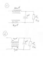
Now Im' wondering whether the fact that the coils are wound on the same core has any effect on the inductance value L, and therefore the required number of turns????
To my mind it must have some effect that the two coils are building on the same magnetic field only 180 degree out of phase!
I have tried to simulate it, using an ideal transformer with a ratio of 1:1 as the coil, and it seems that you only need to aim for half the inductance for each coil compared to using two separate coils (less overall turns needed using only one core, compared to using two separate for the two coils!!!!
Can anyone confirm this?
Thanks in advance.
In the design I'm working on, I'm using an H-Bridge.
I'm using a coil I had laying around, and have wound both coils on the same core.
With high voltage (56 VDC) the coil got very hot. As Eva has pointed out the volt per. turn is quite important for core loss ... more turns less loss. Ok, so far so good
I have ordered new cores (T106-2) to lower the loss through using a more suitable core material for the 250 kHz I'm using.
Question:
Now Im' wondering whether the fact that the coils are wound on the same core has any effect on the inductance value L, and therefore the required number of turns????
To my mind it must have some effect that the two coils are building on the same magnetic field only 180 degree out of phase!
I have tried to simulate it, using an ideal transformer with a ratio of 1:1 as the coil, and it seems that you only need to aim for half the inductance for each coil compared to using two separate coils (less overall turns needed using only one core, compared to using two separate for the two coils!!!!
Can anyone confirm this?
Thanks in advance.
Attachments
Hmmm, would be interested in a prof. manufacture that makes prototypes cheaper than Olimex .... is there a link or a contact?
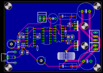
As for the board. It looks ok, but I would probably do the following:
The side where you have the least tracks should be where you place your ground layer.
Try eliminating real estate by moving components closer together to minimize loop size and coupling problems.
.... is there a link or a contact?As for the board. It looks ok, but I would probably do the following:
The side where you have the least tracks should be where you place your ground layer.
Try eliminating real estate by moving components closer together to minimize loop size and coupling problems.
Hello Baldin
Your right, it's half the inductance for each coil, and you found the right way to minimise it!
Fredos
www.d-amp.com
Your right, it's half the inductance for each coil, and you found the right way to minimise it!
Fredos
www.d-amp.com
Maybe you should consider revising the path for the feedback, move it closer to the rest of the circuit, it makes a big loop now.
With this much PCB, you should also consider laying the coil flat, to minimize strayfield, as described by Bruno in The Do’s and Don'ts for Proper Design Implementation
Otherwise it looks ok
With this much PCB, you should also consider laying the coil flat, to minimize strayfield, as described by Bruno in The Do’s and Don'ts for Proper Design Implementation
Otherwise it looks ok
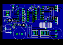
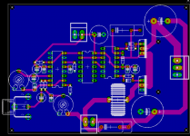
Umm that was not nice
I have had 3 diff ppl redoing my original board, and that is one of them.
And this was another.
The third i deleted because not mutch had changed from my original.
This thing is only gonna run on 100-400KHz, not 1+ MHz as commercial class d amps.
I have had 3 diff ppl redoing my original board, and that is one of them.
And this was another.
The third i deleted because not mutch had changed from my original.
This thing is only gonna run on 100-400KHz, not 1+ MHz as commercial class d amps.
Attachments

Your last one could be good, but just move the trimpot of feedback close as possible to the cap near the modulator to avoid pick up of noise...This is a critical point. Add some ground trace near the feedback signal from the output to the trimpot. Add a decoupling capacitor (0.1 to 1 uF 100V MKT) between power supply of mosfet and the power electrolytics. Add some decoupling to the IR2110, this will help you a lot! Dont forget your snubber too at the output! This will help your stability!
Fredos
www.d-amp.com
Fredos
www.d-amp.com
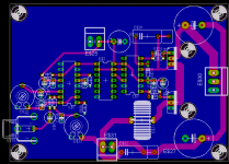
And here is a module built and working nicely.
It has so high gain that it has loud white noise to it.
Heres some pics:
http://user.faktiskt.se/Tekko_Tubeamp/D-amp project/single sided/plugged in/
It has so high gain that it has loud white noise to it.
Heres some pics:
http://user.faktiskt.se/Tekko_Tubeamp/D-amp project/single sided/plugged in/
Hi Tekko
Last design seem good, just add a 0.1uF decoupling cap on your hight side driver power supply. Otherwise, you risk to blow the hight ESR capacitor you use on the bootsrap power supply! Just close more your loop to reduce gain, this will help stability and noise performance.
Fredos
www.d-amp.com
Last design seem good, just add a 0.1uF decoupling cap on your hight side driver power supply. Otherwise, you risk to blow the hight ESR capacitor you use on the bootsrap power supply! Just close more your loop to reduce gain, this will help stability and noise performance.
Fredos
www.d-amp.com
- Status
- This old topic is closed. If you want to reopen this topic, contact a moderator using the "Report Post" button.
- Home
- Amplifiers
- Class D
- level shifters and mosfet drivers