Trileru, I can see that you are heavy into the design of this budget amp. We don't even know if these are now clones of the 2020 and if they adhere to any or all of the designs of the original Tripath chip. As for damaging speakers with the limited 3a psu, if the speakers get the full psu across them, and you can't hear that there is a problem with the sound, then the listener has a problem. I seriously doubt that 3a on a decent speaker for a short period of time is going to harm it, that is if such a condition could exist with this chip. If the inaudible switching noise riding on the output signal bothers you, then someone needs to go to a different class amp. I would be more concerned with long term high DC offset.
I give.
I give.
I played around with a Muse variant. Indeed there is the question of the chip. If it's legit, sub standard or clone. Who knows. It's a roulette ")
The DC offset would be a real problem. But for sensitive speakers, some HF might be bad long term as well. Depends on the speakers, but I wouldn't use such an amp for nice speakers anyway.
It is a nice sounding amp but I've moved away from it since. Class D is mostly for efficiency and cost control. I really don't like having HV riding on my music into the speakers.
Hello all,
I kind of gone through half of the 203 pages of posts on this thread looking for the circuit.
I did find few circuit diagrams; but what I found did not have the Capacitors and Resistors numbered(like C1, C2 etc) at all, or the numbers were random(Like C1 and C2 etc. did not match with any of the versions of boards I have seen here).
So I would like to check, whether we have a post pointing to the updated schematic? Or my only option is to look at one of those schematics and re-trace and remap on my board which one is which?
I am only interested in the tone control section of this becuase while replacing the opamp, my hakko hotair blew off some of the caps. I thought I might just as well replace all of them.
So would like to know what are the values of following SMD capacitors
C25, C40, C24, C41,C43, C26, C27, C23, C22, C42
Thanks in advance....
Last edited:
Changing volume pot fixed some problems for me
after having it sit in my "repair" bin for a few years i finally got around to modding this thing.
The right spkr output would cut out randomly and when adjusting volume. I changed out the original pot for a Bourns PDB182-K420K-203B which was a perfect match. While in there i also changed the big cap from 2200uf to a 5600uf.
Not only did this fix any speaker cutout issues, the noise went down - it always had an audible hiss....much quieter now. I havent tested bass output to see if the larger cap made a difference but its not important to me - I'm using it to power 2 rear surrounds on my PC - mainly for gaming.
The volume potentiometer is a likely suspect. It might just be a bad spot in the pot tracking; measure a few times at different pot settings. Then...
You could jumper both channels across the volume control and see if things equal out. If so, then pot replacement or leaving it jumpered is one fix. Or (and this is a last resort "fix") you could keep the pot installed and tweak the op amp gain for one channel. I would wait until I finished the other mods to do this, though, after another balance check.
after having it sit in my "repair" bin for a few years i finally got around to modding this thing.
The right spkr output would cut out randomly and when adjusting volume. I changed out the original pot for a Bourns PDB182-K420K-203B which was a perfect match. While in there i also changed the big cap from 2200uf to a 5600uf.
Not only did this fix any speaker cutout issues, the noise went down - it always had an audible hiss....much quieter now. I havent tested bass output to see if the larger cap made a difference but its not important to me - I'm using it to power 2 rear surrounds on my PC - mainly for gaming.
I bought one of these "Lepai" amps two years ago and I have given it away. I do not like the sound, it is clear and wide open but lacks punch, and bass.
See the reviews that seem to bear me out:
Lepai LP-2020A+ review: Lepai LP-2020A+ - Page 2 - CNET
You Tube review:
Lepai LP-2020A+ review: Lepai LP-2020A+ - Page 2 - CNET
See the reviews that seem to bear me out:
To get a better fix on the LP-2020A+'s sound I compared it with the least expensive low-power amplifier I had on hand, the $199 Audioengine N22 (22 watts per channel). The N22 is a desktop amp, but unlike most small amps, the N22 is a conventional (not digital) amp. In any case, the two amps sounded equally powerful, but the N22 presented a more sharply focused sound "picture." The bass definition on Beyonce's "4" album was much improved; dynamic punch kicked harder, and the treble detailing was superior. The N22's stereo soundstage was more detailed and spacious than that of the Lepai LP-2020A+. The nearly eight-times-as-expensive amp was clearly better than the Lepai -- but it certainly wasn't eight times better-sounding.
Lepai LP-2020A+ review: Lepai LP-2020A+ - Page 2 - CNET
You Tube review:
Lepai LP-2020A+ review: Lepai LP-2020A+ - Page 2 - CNET
Got a 2020A+ from a friend and need some help before i go through 200 pages:
-power supply, is this sufficient ?
12V 5A 110-240V AC DC Power Supply Adapter Charger For 5050/3528 LED Strip Light | eBay
-before connecting the speakers is there anything to check in order to avoid unpleasant surprises?DC offset maybe?
-how would you describe the sound of these amps?
Many thanks
-power supply, is this sufficient ?
12V 5A 110-240V AC DC Power Supply Adapter Charger For 5050/3528 LED Strip Light | eBay
-before connecting the speakers is there anything to check in order to avoid unpleasant surprises?DC offset maybe?
-how would you describe the sound of these amps?
Many thanks
An externally hosted image should be here but it was not working when we last tested it.
12V/5A is sufficient. If you can manage to find a 13.5V power supply, you can get a little more output power.
The power supply you suggest is for a LED strip and needs a 4700uF capacitor between the power supply output and the amplifier.
Checking the DC levels with a dummy load is very clever. A class D amplifier should only be turned on with a load. Operation without a load may damage the amplifier.
I have got Tripath TC2001/STA505 and Tripath TA2022 boards. The sound of those I will qualify as very good. The TA2020 is reviewed by many people on the Net and all are amazed about the good quality.
Last edited:
12V/5A is sufficient. If you can manage to find a 13.5V power supply, you can get a little more output power.
The power supply you suggest is for a LED strip and needs a 4700uF capacitor between the power supply output and the amplifier.
Oops,didn't' know that.
Can you suggest a decent cheap one in the UK then?
I can show you examples, but in the UK you have one on Amazon:
13.5V 5A 68W AC/DC Power Supply Adapter Transformer Interface 5.5x2.5mm Suitable for Security equipment LCD LED lighting Communications equipment Digital products UL and FCC approved With Power Cord: Amazon.co.uk: Computers & Accessories
13.5V 5A Switching Power Supply AC to DC Adapter Dual Cable Converter Voltage Regulator Power Adapter 5.5x2.1 2.5m-in AC/DC Adapters from Home Improvement on Aliexpress.com | Alibaba Group
Universal 5.5x2.1 2.5m 13.5V 5A AC to DC Power Adapter Dual Cable Converter for Electronic Instruments Power Supplies-in AC/DC Adapters from Home Improvement on Aliexpress.com | Alibaba Group
The only regret I have seen TA2020 owners express is the limited output power. The TA2020 can handle 16V but inactive and 14.4V active. So, many suggest using above 12V to get maximum output power. I wouldn't go above 13.5V though.
You should still give it 4700uF-6800uF at the output to buffer the supply line.
I can show you examples, but in the UK you have one on Amazon:
13.5V 5A 68W AC/DC Power Supply Adapter Transformer Interface 5.5x2.5mm Suitable for Security equipment LCD LED lighting Communications equipment Digital products UL and FCC approved With Power Cord: Amazon.co.uk: Computers & Accessories
13.5V 5A Switching Power Supply AC to DC Adapter Dual Cable Converter Voltage Regulator Power Adapter 5.5x2.1 2.5m-in AC/DC Adapters from Home Improvement on Aliexpress.com | Alibaba Group
Universal 5.5x2.1 2.5m 13.5V 5A AC to DC Power Adapter Dual Cable Converter for Electronic Instruments Power Supplies-in AC/DC Adapters from Home Improvement on Aliexpress.com | Alibaba Group
The only regret I have seen TA2020 owners express is the limited output power. The TA2020 can handle 16V but inactive and 14.4V active. So, many suggest using above 12V to get maximum output power. I wouldn't go above 13.5V though.
You should still give it 4700uF-6800uF at the output to buffer the supply line.
Thanks for replying,
but i still don't understand the capacitor thing you say, you mean replacing the stock 2200uF or something else?
On the capacitor:
On the photo you posted, I see one bigger capacitor on the left side. It is likely to be the (only) power line decoupling capacitor. Probably 1000uF or 2200uF. Leave that in!
When you want good sound from an amplifier, it is important that the supply voltage is rather constant. But, an amplifier is a very dynamic load that may suddenly require 2A just to mention a figure. That means, either the power supply is able to react very fast and supply the extra current or the current is for a start drawn from the power line buffer capacitor. When the current is taken from the buffer capacitors, the voltage sags (lowers). That influences the sound.
The power supplies you buy ordinarily are general purpose and not very fast in regulation. Thus, you rely a lot on your buffer capacitors. Say, your buffer capacitor is 2200uF - that isn't much. But, you can add capacitance by putting more capacitors in parallel. My suggestion is to add 6800uF, which together with the internal capacitor, would leave a total of 9000uF. Much better than 2200uF (300% improvement).
To be added at the output of the power supply but before the power input connector of the amplifier.
Without such an extra capacitor your amplifier will play, but when suddenly you have bass transients they may be less well controlled and worse your mid range may be affected. The TA2020 is so good a chip that it deserves a good supply. And, 6800uF/25V will cost you around a Pound.
Last edited:
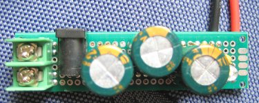
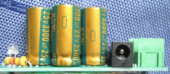
External capacitor buffer
Appended you find two photos of how an external capacitor buffer can be constructed. The one shown uses three 3300uF capacitors, thus, in total 10000uF.
It has got a DC input connector fitting the output connector of the power adapter. Further, it has alternative screw terminals for power input. The output is the black and red wires going to the amplifier power input.
Also, a LED-diode is added to show when the power is ON.
Attachments
Last edited:
The reason why I asked if you have buffer capacitors with you is that often I "cannibalize" an old radio/amplifier/receiver or such. Such buffer capacitors are standard in almost any apparatus using a power (net-) transformer. Eventually, you can ask at the local "recycling center" if you can have an old power board with such a buffer capacitor. Then, you do not need to buy a plurality of capacitors, pay for having them sent and waiting for them to arrive.
Most amplifiers (except for the high-end ones) are delivered with a minimum of power line decoupling capacitors. They can be costly, are large (difficult to fit into a compact design) and many designers are less concerned about a dynamic behavior that is only an occasional problem.
Most amplifiers (except for the high-end ones) are delivered with a minimum of power line decoupling capacitors. They can be costly, are large (difficult to fit into a compact design) and many designers are less concerned about a dynamic behavior that is only an occasional problem.
Last edited:
Excellent thanks
The stock one is 2200uF.
Is there a schematic on how to connect the extra capacitor?
Schematic appended. Sorry for the hand-drawing.
The plug from the power adapter has normally "-" on the outside and "+" on the inside of the coaxial contacts. The outside (-) is connected to the minus terminal of the capacitor and the inside (+) to the plus terminal of the capacitor. So simple. Then the + and - terminals of the capacitor are connected to the corresponding power input terminals of the amplifier.
The capacitor may be a single one or more capacitors connected in parallel. You just add the value of each capacitor to get the total value.
Attachments
- Status
- This old topic is closed. If you want to reopen this topic, contact a moderator using the "Report Post" button.
- Home
- Amplifiers
- Class D
- Lepai T-Amp with TA2020