I think you have some misconceptions around electronic functioning. LEDs conduct all the way down to zero volts, albeit nonlinearly. Above 100uA say, the LED voltage will be in the region of 2V for example, more or less constant at higher currents. But as the tube current drops down to the microamp range, the LED forward voltage rapidly drop towards zero. But it doesn't suddenly stop conducting; only SPICE diodes can do that.If the LED provides 2v and the signal goes to (-)1v what does the LED see as a forward voltage? The total is (+)1v. Is that enough forward voltage to drive the LED for conduction? Or is the LED now in shutoff for all practical purposes?
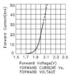
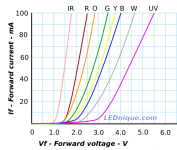
That's just a sketch, this graph is more correct.
IV curves | LEDnique
IV curves | LEDnique
Attachments
Last edited:
Two things to keep in mind:The current through an LED is nearly 0 mA as the forward voltage falls through 1v. -.7v.
1) If you apply a (-1 V) swing to the grid of the forward-biased triode, you do not get a (-1V) swing at the cathode - you only get a small fraction of that. The rest of the voltage is lost in the internal cathode impedance of the valve, which can be surprisingly high. For a half-12AX7 with a 100k anode load, the cathode impedance is in the region of 2000 - 2500 ohms when the valve is conducting 1 mA or so. And even higher if you push the valve into cut-off!
The dynamic resistance of the LED is much lower than 2000 ohms, which is why only a small fraction of that (-1 V) swing appears across the LED.
2) As several people have pointed out, the diode current is exponential with applied voltage. An exponential current grows so fast as voltage increases, that with the graph scaled to accommodate the largest current, it looks as though there is zero current near the left edge of the graph.
But in fact there is still current flowing, it's just too small to see easily on the same scale as the larger currents at higher voltage.
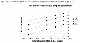
This is easily revealed if you plot the logarithm of the diode current vs forward voltage, rather than plotting diode current vs forward voltage. The logarithm "straightens out" the exponential nature of the diode current, letting you see what's going on even when forward voltages are small.
A quick Google search produced the attached image (taken from here: Plot of diode voltage versus natural logarithm of applied current under... | Download Scientific Diagram )
As you can see, the plots are almost perfectly straight lines (meaning the current is almost perfectly exponential) all the way down to 0.325 V or so. The currents are down to approximately 0.14 nanoamps at the left edge of the graph (this corresponds with the natural logarithm being -9.5 on the x axis of the graph.)
So we can see why the graph doesn't extend further to the left - the currents are already quite small, and it would take rather specialized instruments to measure these small currents. But there is no sudden cutoff of current anywhere to be seen on the graph - you can smoothly throttle a diode all the way down to less than a tenth of a nanoamp without the current ever shutting off.
So: we know the diode holds no surprises down to well below one nanoamp of current flow. The next question is, how much negative grid voltage would it take to drop the valve's current all the way down to a nanoamp?
Well, the answer is that we never actually throttle a valve down to a nanoamp! If we were operating the valve at 1 mA quiescent current, it's not often that we would manage to swing that current down to a tenth of that - 0.1 mA (which is 100000 nanoamps).
Suppose we really slammed that grid with a big negative voltage, and managed somehow to cut off the triode all the way down to 0.01 mA, one hundredth times smaller than the quiescent current. Well, 0.01 mA is still 10,000 nanoamps!
And where is 10,000 nanoamps on that graph? 10,000 nA is 10 microamps, and the right edge of the graph (x = -6) corresponds to about 0.434 microamps. So 10 microamps is actually well to the right side of the entire graph, where those straight lines are just as straight!
The whole puzzle of "What happens to to the diode when the valve forces the voltage across it to become less than 0.5 volts?" turns out to be a red herring. Even if you apply a large negative grid voltage and shut off the valve all the way to 10 microamps, the diode is still happily conducting, and from the graph, we can see that the diode is still sitting at maybe +0.7 volts. (I'm looking at the 30 degrees C line, and extrapolating it to the right of the graph to reach 10 uA.)
What this means is that you cannot actually use the control grid of the valve to force the diode deep into cutoff. The valve cuts off long before the diode does - the cathode sits at roughly +0.7 volts, the grid sits at whatever enormous negative voltage you used to shut the valve down to 10 uA, and the diode is still quite happily conducting.
All this is quite counter-intuitive, particularly if you are used to thinking "It's a cathode-follower, the voltage at the cathode follows the voltage at the grid. So how can the cathode be at +0.7V while the grid is at -10 V?"
But in fact, that statement should be qualified: the voltage at the cathode only follows the voltage at the grid if the external cathode load has a much higher impedance than the internal cathode impedance. And with a forward-biased diode as the cathode load, you can never meet that condition - the diode always has lower impedance than the valve itself has "inside" it, even when you cut-off the valve!
Merlin, PRR, and others on this thread have all pointed at several of these points in previous posts. I'm just pulling it all together in this post, and trying to wrap it in enough words to be very clear and easy to understand the whole big picture.
-Gnobuddy
Attachments
Just to avoid any concern, the LED dynamic resistance (ie. external cathode load) does increase as conduction current decreases. The amber 5mm LED I use has R~60 ohm over the increment 0.7 to 1mA, increasing to ~500 ohm over the increment 0.05 to 0.1 mA, but I didn't continue any measurement below 0.05mA.
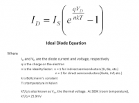
It does indeed! If you take the Shockley diode equation (see attached image), assume the "ideality factor" equals unity, assume the diode is at room temperature, differentiate the equation,and work out the dynamic resistance (dV/dI), you come up with an extraordinarily simple answer: the dynamic resistance (in ohms) equals 26/(diode current in mA).Just to avoid any concern, the LED dynamic resistance (ie. external cathode load) does increase as conduction current decreases.
So for an ideal silicon diode, the dynamic impedance is 26 ohms at 1 mA forward current, 260 ohms at 0.1 mA, 2600 ohms at 0.01 mA, and so on. Super-simple!
In practice this result works well at currents well under a milliamp, but isn't usually correct at larger currents, where ohmic resistance from bonding to the silicon die, bulk resistance of the P and N regions, and other factors start to cause increasing errors.
For the materials used in typical LEDs, the "ideality factor" is 2 rather than 1, and this has the effect of doubling the dynamic resistance. So now we should have 52 ohms at 1 mA, 520 ohms at 0.1 mA, and so on. Note that those numbers aren't too far from the numbers Trobbins measured.
")
And back to the "What if the diode shuts off?" concern, notice that (26/I) never becomes infinity until I is mathematically zero...even if you have only ten microamps of diode current (which is 0.01 mA), the dynamic impedance of the diode is 2.6 kilo ohms, not infinity.
-Gnobuddy
Attachments
Well, let me repeat what I said before, but you ignored:
1.) For currents around 10 mA one LED is fine.
For currents around 30 mA 2 in parallel are fine, and they pretty well share the current.
2.) If current is less that 10 mA, use an external bias current for the LED, like 10 mA from a clean source.
3.) When using LED cathode bias, use Gyrator to load anode of the triode. Such a way you will get always maximal swing with lower distortions, no matter if the tube ages, or temperature decreases voltage drop on the LED.
See, for example, my very old 4P1L thread where I used this.
One more 4P1L SE
I can't speak for anyone else, but I did read what you said before, and I promise I didn't ignore it.Well, let me repeat what I said before, but you ignored
Using what amounts to a current source anode load (one that automatically adjusts itself to have the right voltage at the anode) makes plenty of sense for applications where low THD is the goal.
I am from the other camp, where I actually want lots of low-order THD from a triode, in order to improve the sound of that evil instrument that cannot be mentioned on this forum without cat-calls and cursing and demands for an exorcist. So I want a relatively low anode load impedance, rather than a very high one. For me, 68k is about right for a half-12AX7, and 100k is as high as I ever want to go. So, for me, a gyrator is not the right solution.
-Gnobuddy
...misconceptions around electronic functioning. ....as the tube current drops down to the microamp range....
I think you are closing in on an important misconception.
(as you know) Audio vacuum tubes NEVER approach a few microamps. We normally work them at some current ample to overwhelm load and stray capacitance, which normally comes to around 1mA idle current.
From there we swing both ways but NOT to zero and infinity (or 2mA). Distortion would be gross.
A tube at 1mA, we'd normally swing 0.5mA to 1.5mA. A 3:1 range of currents approaches 5% THD for most tubes.
There's no "cut-off" of tube or LED.
(Unless the LED is exceptionally leaky; true in 1974 "surplus" (reject) devices but fabrication is far better today.
Dynamic resistance in LEDs is approximately inversely proportional to current.Just to avoid any concern, the LED dynamic resistance (ie. external cathode load) does increase as conduction current decreases. I didn't continue any measurement below 0.05mA.
LED tube biasing, pros and cons
Last edited:
Only if you want more distortion and more global warming. Otherwise don't.
Vice verse, actually. Think again about results of your measurements and what they mean.
Dynamic resistance in LEDs is approximately inversely proportional to current.
LED tube biasing, pros and cons
Better read this and try to understand the difference between "inversely proportional" and "exponential".
LED tube biasing, pros and cons
This has been debunked in three threads in as many months (maybe that's why your 'tips' were ignored). Boosting LED current increases tube distortion. Please don't keep repeating this needless myth to beginners.Vice verse, actually. Think again about results of your measurements and what they mean.
Last edited:
Hmm, I think you need to take your own advice there.Better read this and try to understand the difference between "inversely proportional" and "exponential".
Last edited:
This has been debunked in three threads in as many months (maybe that's why your 'tips' were ignored). Boosting LED current increases tube distortion. Please don't keep repeating this needless myth to beginners.
I see the graph and trust your measurment. But i do not understand why it should increase distortion, could we have an explanation of this effect ?
I see the graph and trust your measurment. But i do not understand why it should increase distortion, could we have an explanation of this effect ?
It can increase distortions if slightly higher voltage drop on a diode is too high to bias his tube properly. Dynamic resistance of the diode is lower when biased by constant current, and it is more linear on the same current swing, hence added by it distortions are lower. Obviously, he would need a different diode material, for a different voltage drop. That means, he is barking on the wrong tree.
Wavebourn has half the anser, but he is missing the point that distortion in the tube degrades at a more or less constant rate as bias is increased. There is no "too high to bias his tube properly" threshold; it's a smooth gradient from less distortion to more distortion. When you boost the LED current you reduce it's internal resistance, yes, but the increase in LED voltage also causes the tube's internal cathode resistance to increase even more. So overall it's a false economy. Caveat emptor.I see the graph and trust your measurment. But i do not understand why it should increase distortion, could we have an explanation of this effect ?
headbash: <-- me trying to explain to Wavebourn )Now, you may see in one of the threads below where PRR points out that you could counter the increase in tube distortion by increasing the HT voltage (probably by mu times the change in bias voltage). However, this again misses the point that after boosting your LED, then dutifully increasing the HT voltage (as if we all have adjustable HT supplies...), you'd still get even lower distortion by removing the boosting from the LED again!
LED tube biasing, pros and cons
LED bias for 6N1P driver
LED bias for 6N1P driver
LED bias for 6N1P driver
Last edited:
<-- me trying to explain to Wavebourn. Explanantions here:
LED tube biasing, pros and cons
LED bias for 6N1P driver
LED bias for 6N1P driver
LED bias for 6N1P driver
Try harder. It may finally help you to understand simple math and physics behind all this.
- Home
- Amplifiers
- Tubes / Valves
- LED tube biasing, pros and cons