LED forward voltage is pretty consistent within a given batch, and very much so over long time periods. (Like 30 years in the case of some I have around here.)
And you can select ones with appropriate Vf for your application.
They do obviously have a temperature dependence which is sometimes provided in the data sheet.
Look for ones with low dynamic impedance. (Not always specified)
Where Vf < 1.5V is needed look at infrared leds.
Bear in mind that using LED cathode bias is equivalent to fixed bias at the Vf of the given diode, and that consequently unless you use a CCS based load the plate current will vary significantly from tube to tube.
I can offer you this: I have never, in my entire life, managed to damage an LED by handling it. This includes LEDs bought in the last few years, some of which have extremely high efficiency (20,000 mcd.) And I've never taken any electrostatic precautions when handling them, either - no grounded wrist strap, etc.Are they really so fragile?
I can also offer you this: while enough electricity (joules) will blow up any semiconductor device, MOSFETs (and CMOS circuitry containing MOSFETs) were the first semiconductor device to be static sensitive, in the sense that they could be permanently damaged by relatively small amounts of electric charge generated during normal handling.
So why were MOSFETs so easily damaged, while diodes, JFETs, and bipolar transistors (BJTs) were not? MOSFETs used a very thin layer of, essentially, silica glass (SiO2) as insulation between the gate and the source / drain. This insulation has extremely high resistance, so it is easy to build up a high voltage on it by handling. And when the voltage is high enough, a microscopic bolt of electricity essentially punches a hole through the microscopically thin layer of SiO2, permanently damaging it.
By comparison, diodes, JFETs, and BJTs (all of which contain diodes, which are NP or PN junctions) never have that much insulation resistance. PN junctions flow current relatively freely in one direction, and leak some current in the other - they are nowhere near as good insulators as a thin layer of glass! So a small amount of electric charge built up on your hands will simply be discharged through one of these PN junctions, without doing it any harm. No physical damage is done to the junction, no holes blown in anything.
So what about LEDs? They used to be just plain old PN junctions, albeit made with materials other than pure silicon in the mix (including indium, gallium, etc.) so as to alter the band-gap, and therefore emit visible light.
Since LEDs were just diodes, we could expect essentially the same characteristics as any other semiconductor diode, except for the different forward voltage. Crucially, they contained no insulating layer of SiO2 to be permanently damaged on the microscopic scale by small amounts of electric charge. Which is why I've never taken any handling precautions with them.
I note that in recent years the electronics vendors I buy from have started shipping LEDs in static-sensitive bags. I assume this is simply a matter of standard procedure: they tell their employees to stuff all semiconductors into static-sensitive bags, regardless of whether those devices happen to be particularly sensitive to static, or not.
I should add that, clearly, LEDs have mutated into rather different animals in recent years, and some are up to a thousand times more efficient than the ones from, say, the 1980s. I suppose it's not impossible that there is something very different about the new LEDs, and that these are now genuinely static-sensitive. But so far, I have not yet turned up an LED datasheet that specifies this, and so far, every discussion I've found on the Internet about static-sensitive LED fears, has been based on the fact that Mouser or Digikey or Jameco has shipped LEDs in a static-sensitive bag with a generic static-sensitive warning label.
So, until a manufacturer's datasheet tells me otherwise, I see no reason at all to worry about LEDs being static-sensitive.
-Gnobuddy
Expensive LED's are made for getting more light for less power, not for biasing valves.For valve bias you just need to buy the cheapest led's in great quantity, select what you need and if there's no consitency, you make it constant by force, that is why SY biased it's led's externally.
Expensive LED's are made for getting more light for less power, not for biasing valves.For valve bias you just need to buy the cheapest led's in great quantity, select what you need and if there's no consistency, you make it constant by force, that is why SY biased it's led's externally.His method is especially recommended when using low anode current and low transconductance valves as ecc83.As kevin said , infrared led's are very good.I would use also a series resistor with a lower value led so that i would give a little feedback to tah system .parallel 100nf ...1uf over the led should also help.I'm looking at some data sheets and seeing wide Vf tolerances for some LEDs. <snip>
So we have 1 mA through each triode of the ECC83/12AX7, and have to draw 5 -10 mA from a 350 volt B+ rail to bias each cathode LED at 1.8 or 2.2 volts?...Sy...biased...externally...method especially recommended when using low anode current...ecc83.
That is rather ridiculous in terms of efficiency and B+ current draw, not to mention the several watts of dissipation, excess heat, and wasted power in the LED dropper resistors.
To me, using an additional external resistor to bleed extra current into cathode LEDs only makes sense if you have a suitable low-voltage positive supply rail handy. For example, if you were using 12.6 V DC to power the 12AX7 heaters, and ground the negative end, you could use the +12.6 V rail to feed extra bias current to those cathode LEDs. The low voltage wastes far less heat, and the high current demands of the heaters make a few extra milliamps inconsequential.
-Gnobuddy
The noise would be lower with an LED, no matter the stage gain , but the distortion generated by the valve in high gain (cap//resistor=led ) are higher than using a resistor , while if you're using global feedback with higher gain of the driver would give lower distortion figures and clipping can be avoided.
I used to use a lot of LED bias, until I started using global negative feedback to the cathode of the driver tube. In my testing I tried several different configurations, and found that using an LED standing on a small resistor with a feedback resistor to the junction worked very well for increasing gain, while allowing implementation of feedback. However, I found in most instances that even if the distortion of the stage itself would go down, the overall distortion of the whole amplifier went up at higher orders, similar to results one found using a capacitor-bypassed resistor. Negligible, but noticeable on paper for sure. Add some global feedback with its' own higher order distortion byproducts, and it looks a little funky. Zero-GNfb designs it did increase the gain and lower the distortion, and showed lower distortion than a capacitor-bypassed resistor would (but not as low as an unbypassed resistor) but my preference now is to use a high-mu tube with an unbypassed cathode resistor instead, and make up the difference in gain by tube choice and bias point for the outputs. I find that the distortion spectra from an unbypassed resistor (with feedback resistor from the output transformer secondary to the cathode) is lower order, and primarily second-harmonic. I can't comment on which "sounds" better, as they all sound pretty nice when done right, but I like the idea of lower order dominant distortion spectra when I can design for it.
Based on my experience and long-forgotten measurements, so take that for what you will. Still a good option for gainstages in SE amps that want maximum gain and don't run feedback to the cathode, and they work well if you run enough current through the chosen LED. I had good success even at sub-mA currents, when choosing low current LEDs. Average LEDs get fairly inconsistent at low current unless specified for it. (as usual, the datasheet is your friend!)
Last edited:
Greetings to the forum and Gnobuddy.

Norman.
At first I thought, who cares? But you make a good point.So we have 1 mA through each triode of the ECC83/12AX7, and have to draw 5 -10 mA from a 350 volt B+ rail to bias each cathode LED at 1.8 or 2.2 volts?
That is rather ridiculous in terms of efficiency and B+ current draw, not to mention the several watts of dissipation, excess heat, and wasted power in the LED dropper resistors.
That could work! Also an asymmetric current mirror could be worked in, where different stages could be tailored from one (low) current reference, I haven't thought it through or even read the whole thread thoroughly, so just a brain fart.Gnobuddy said:To me, using an additional external resistor to bleed extra current into cathode LEDs only makes sense if you have a suitable low-voltage positive supply rail handy. For example, if you were using 12.6 V DC to power the 12AX7 heaters, and ground the negative end, you could use the +12.6 V rail to feed extra bias current to those cathode LEDs. The low voltage wastes far less heat, and the high current demands of the heaters make a few extra milliamps inconsequential.
Norman.
...if you were using 12.6 V DC to power the 12AX7 heaters, and ground the negative end.....
....then you could rig 100r and 20r to get ~~2.1V at an impedance MUCH lower than most any tube's cathode, with less "waste" heat than the tube's own heater.
Or for more thriftiness, ground the + end, divide across the - end, to make grounded-cathode grid-bias connections with near-zero current/heat. Grid-cathode, cathode-grid, what is the difference?
OK, to get back to the 6j5 scenario.... I actually am powering them with 6.3vdc, as a side effect of trying to chase down some hum issues.So we have 1 mA through each triode of the ECC83/12AX7, and have to draw 5 -10 mA from a 350 volt B+ rail to bias each cathode LED at 1.8 or 2.2 volts?
That is rather ridiculous in terms of efficiency and B+ current draw, not to mention the several watts of dissipation, excess heat, and wasted power in the LED dropper resistors.
To me, using an additional external resistor to bleed extra current into cathode LEDs only makes sense if you have a suitable low-voltage positive supply rail handy. For example, if you were using 12.6 V DC to power the 12AX7 heaters, and ground the negative end, you could use the +12.6 V rail to feed extra bias current to those cathode LEDs. The low voltage wastes far less heat, and the high current demands of the heaters make a few extra milliamps inconsequential.
-Gnobuddy
So, if you don't mind laying out the scenario of adding some current safety resistors to the LED on the cathodes of the 2 6j5 tubes. Cheers, 808
Last edited:
It's also a waste of time because it simply increases tube distortion (by increasing the bias voltage slightly) with no obvious benefit.So we have 1 mA through each triode of the ECC83/12AX7, and have to draw 5 -10 mA from a 350 volt B+ rail to bias each cathode LED at 1.8 or 2.2 volts?
That is rather ridiculous in terms of efficiency
So, you are opposed to using a LED for tube cathode bias in a 12ax7 or all tubes?It's also a waste of time because it simply increases tube distortion (by increasing the bias voltage slightly) with no obvious benefit.
That's an excellent idea!....then you could rig 100r and 20r to get ~~2.1V at an impedance MUCH lower than most any tube's cathode.
It's startling just how much impedance there is looking into the cathode of a typical triode preamp tube. In a transistor it is only (1/gm), nominally 26 ohms at 1 mA collector current. By contrast, in a half-12AX7 triode at 1 mA anode current, you have 600 - 700 ohms from the (1/gm) term, an additional 700 - 800 ohms from the (ra/mu) term, and yet another 1000 ohms from the (Ra/mu) term if you have a 100 kilo ohm anode load. Around 2 - 2.5 kilo ohms total impedance looking into the cathode!
So, for a 12AX7, we could easily have 200 - 300 ohms external impedance at the cathode of a typical 12AX7 gain stage, and still have negligible impact on the voltage gain.
-Gnobudddy
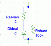
LED ...Look for ones with low dynamic impedance. (Not always specified)...
If you are working well below Rated Current, there should be no problem.
Inspecting the (cracked open) device and pictures in sites/books, an LED is not a complicated thing. It is a single junction (white may be different). In its heart, it obeys the well-known rules of flow in a junction (a re-casting of the old rules about water flow in a ditch). At the crystal level, that's about all that can happen. It will be exponential over a very wide range. It will deviate when "practical" flaws intrude. Obviously any crystal has defects in bulk and on surface, which approximate a leakage resistance or current. And the contacts can't have zero Ohms resistance.
The series resistance "IS" controlled, so that customers who use the LED at or above (pulse) its rated current do not have to apply distressing voltages. Because LEDs should always be current-driven, the specified operating voltage may be the high end of typical. "Usually 3 Ohms, unless the bond is bad, then we allow 10 Ohms before rejecting a part." 10r at 20mA is 0.2V, which is about the uncertainty seen in a large run of not-matched LEDs.
Attachments
I read Merlin's post as saying "It is a waste of time to use an additional resistor to feed extra current to the bias LED".So, you are opposed to using a LED for tube cathode bias in a 12ax7 or all tubes?
He's not saying it's a waste to use an LED for cathode bias - he's saying it's a waste to use additional circuitry to increase current through the LED in hopes of getting less distortion.
-Gnobuddy
Exactly, just use an LED that gives you the bias you want, and don't overthink it. Bypass with a big capacitor if it is a noise-critical circuit position. It really is that simple.
Ok, excellent!
I thought too there was a general consensus that LED bias was an overall, good thing, until, ???ofNJ, started posting his graphs, which i noticed have all disappeared, about the possibility of low current cut off, which it turns out was a problem with his measurements?
Thank you for clearing up my misconceptions.
Thank you for clearing up my misconceptions.
That was easy. Have you answered the question for yourself yet, at what signal level as it swings negative on the grid, does the voltage begin to shut off the LED? If the LED provides 2v and the signal goes to (-)1v what does the LED see as a forward voltage? The total is (+)1v. Is that enough forward voltage to drive the LED for conduction? Or is the LED now in shutoff for all practical purposes?
- Home
- Amplifiers
- Tubes / Valves
- LED tube biasing, pros and cons