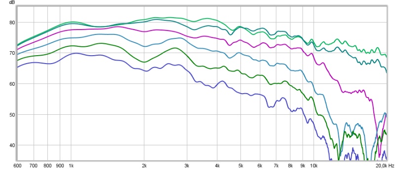
So far I've been focused on controlling directivity for the tweeter (as seen in the 3D-printing thread here) which looks something like this (0-75 deg):
I feel I'm closing in on something that I want to try in a speaker (not just measure). But then I need something for frequencies between ~150 Hz and 1500 Hz (below 150 I have subwoofers and that should be below the Scroeder frequency, i.e. directivity is not necessary). I need to place the speakers close to the front wall (~20 cm) so the most suitable polar patter should be supercardioid:
(Image borrowed from kimmusaunisto.net)
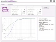
I found this website:
Cardioid bass
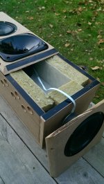
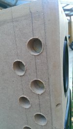
And decided to give one of my test speakers a set of holes to test the leaky box approach:

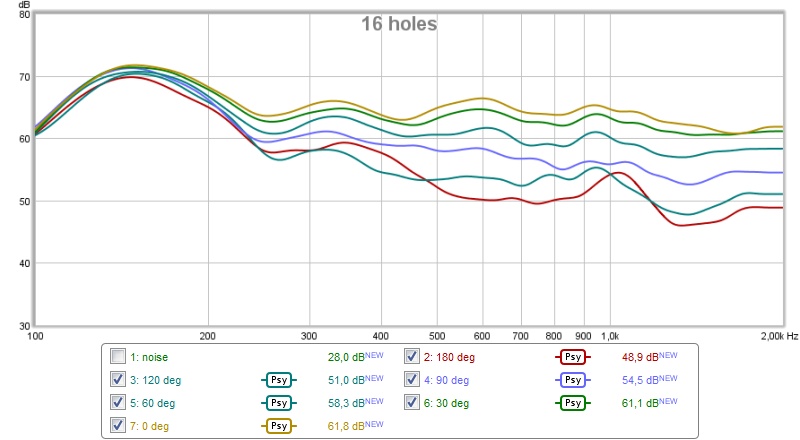
This is with 16 1" holes on each side, slightly above Sd for two 5" woofers.
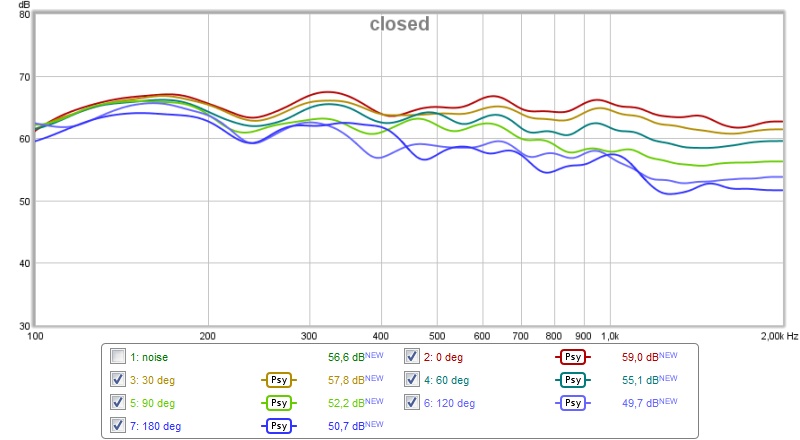
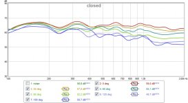
First a measurement of the speaker before any holes where made (0, 30, 60, 90, 120 and 180 deg):
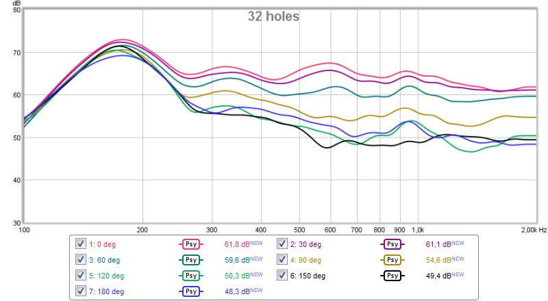
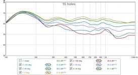
Then I made 8 holes on each side and measured again (0, 30, 60, 90, 120 and 180 deg):
I assume the hump is due to the fact that the box behaves like a ported box at low frequencies. Can that be solved by adding more holes?
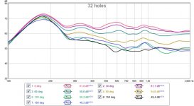
This is with 16 holes on each side (0, 30, 60, 90, 120, 150 and 180 deg):
The hump is moved up in frequency, but separation between lines is better. Lowest SPL is observed at 150 deg, then 120 and then 180 deg.
All measurements at 1.5 m distance, 1.5 m above ground, no gating, psychoacoustic smoothing.
I have not added any resistive element to the holes, but there is some ~polyfill in the speaker. The results are decent, what would adding resistance do?
Questions:
1. What should I do to get directivity to reach down below 200 Hz? Add more holes, resistivity?
2. What driver parameters should be suitable for this type of application? Any examples below 100 USD each for ~7" drivers?
/Anton
I feel I'm closing in on something that I want to try in a speaker (not just measure). But then I need something for frequencies between ~150 Hz and 1500 Hz (below 150 I have subwoofers and that should be below the Scroeder frequency, i.e. directivity is not necessary). I need to place the speakers close to the front wall (~20 cm) so the most suitable polar patter should be supercardioid:
An externally hosted image should be here but it was not working when we last tested it.
(Image borrowed from kimmusaunisto.net)
I found this website:
Cardioid bass
And decided to give one of my test speakers a set of holes to test the leaky box approach:
This is with 16 1" holes on each side, slightly above Sd for two 5" woofers.
First a measurement of the speaker before any holes where made (0, 30, 60, 90, 120 and 180 deg):
Then I made 8 holes on each side and measured again (0, 30, 60, 90, 120 and 180 deg):
I assume the hump is due to the fact that the box behaves like a ported box at low frequencies. Can that be solved by adding more holes?
This is with 16 holes on each side (0, 30, 60, 90, 120, 150 and 180 deg):
The hump is moved up in frequency, but separation between lines is better. Lowest SPL is observed at 150 deg, then 120 and then 180 deg.
All measurements at 1.5 m distance, 1.5 m above ground, no gating, psychoacoustic smoothing.
I have not added any resistive element to the holes, but there is some ~polyfill in the speaker. The results are decent, what would adding resistance do?
Questions:
1. What should I do to get directivity to reach down below 200 Hz? Add more holes, resistivity?
2. What driver parameters should be suitable for this type of application? Any examples below 100 USD each for ~7" drivers?
/Anton
Attachments
Last edited:
Alright, I'll try that (fiberglass).Try filling the enclosure with different amounts of denim(or fiberglass) insulation for better separation down low.
Yeah, how do I remove that effect? Would it help to router the edge holes effectively making the ports significantly shorter?Looks like it is "porting" and that those holes are not holes at low frequencies where the volume velocity is higher
/Anton
I have extensive experience with the 'black art' and science of passive gradients. They are difficult to get right, but when you do you'll be treated to much improved transparency and less coloration in the midrange. With a well-optimized cardioid you can achieve rear rejection better than 20 dB. Combine the cardioid with a good waveguide and you can achieve constant directivity to a much lower frequency than would be possible with traditional loudspeakers.
What you need to remember is that you get the best possible rear-rejection the transfer function of the front-wave that wraps around to the back of the enclosure and the transfer function of the back-wave that exits the slots to the rear of the enclosure are identical, besides inversed polarity. The difficulty lies in the fact that you always measure a combination of the front-wave and back-wave. You know that when you get good rejection, both amplitude and phase are well-matched. Whenever the results are less than perfect, it is difficult to tell if the back-wave is damped too much or too little, or if it is delayed too much or too little.
The kind and amount of damping material in the enclosure, the dimensions of the enclosure and the size and locations of the holes all have an effect on the back-wave. You can't really generalize and say that a certain amount of damping material works best, or that a certain number of slots works best. It is the combination of all factors that determines the transfer function.
In my experience you need clean anechoic measurements with a significant frequency resolution to get a good grasp of what is going on. In-room measurements simply won't do. I usually perform my measurement on a large parking lot, where I can get a clean window of about 80 ms.
While I agree that outdoor measurements are best I've been getting decent enough results doing indoor ground-plane. I'll use a longer gate in REW with a freq dependant window. The freq resolution isn't very good of course so I wouldn't really use this for eq but the directivity measured correlates well with what I measure outdoors.
You've got a lot of experimenting ahead of you......
You've got a lot of experimenting ahead of you......
My friend, a relative of Occam, advises to put the absorber on the wall behind the speaker, instead of as resistance inside the speaker. Absorbing the rear wave is a lot easier than cancelling it, although not nearly so elegant.
Absorbers on the wall is not only a less elegant solution, it is also a lot less effective. A gradient has directivity all the way to its lower cut-off, while an absorber has high-pass characteristics. The most problematic frequency range of a front-wall reflection is the lower hundreds. You need in the order of half a meter of damping material for the absorber to be effective at 100 hertz. Not an attractive solution in my opinion.
2. What driver parameters should be suitable for this type of application? Any examples below 100 USD each for ~7" drivers?
Anton, are you looking to design a passive crossover?
By the way, if I were you I wouldn't use fiberglass or rockwool. Both are presumably carcinogenic.
Last edited:
If you only care about 300 Hz and up, which is where Nate achieved directivity, then 6" of fiberglass spaced 2" from the wall will do nicely. Considering the system solution, I would use more than that to help tame longitudinal room modes.
Not to say I don't appreciate Nate's good work; he may well have a room where the simple low tech approaches like absorber or baffle wall don't apply.
Not to say I don't appreciate Nate's good work; he may well have a room where the simple low tech approaches like absorber or baffle wall don't apply.
Attachments
I'll measure the fiberglass option first, then look at other materials.You need some kind of flow resistor to dampen the 'porting' AND to create (super)cardioid behaviour. Carpet without foam backing is said to work well.
Just curious, is that horn an 18Sound XT120?
It's indeed the XT120 in the photos (coupled to a Beyma CD10Fe), not in the measurement in the first post though. I liked the polars, but disliked the high sensitivity (noisy with my amplifiers) and crappy transient response.
I agree, decent result from a very simple test. A nice coaxial together with a round (spherical) enclosure with holes could be really nice!That's pretty impressive. I wonder if this could be done with a coaxial woofer/horn driver (like the Volts at diysg) to get it all to resemble a point source with directivity?
I'm glad to have you in this thread!I have extensive experience with the 'black art' and science of passive gradients. They are difficult to get right, but when you do you'll be treated to much improved transparency and less coloration in the midrange. With a well-optimized cardioid you can achieve rear rejection better than 20 dB. Combine the cardioid with a good waveguide and you can achieve constant directivity to a much lower frequency than would be possible with traditional loudspeakers.
What you need to remember is that you get the best possible rear-rejection the transfer function of the front-wave that wraps around to the back of the enclosure and the transfer function of the back-wave that exits the slots to the rear of the enclosure are identical, besides inversed polarity. The difficulty lies in the fact that you always measure a combination of the front-wave and back-wave. You know that when you get good rejection, both amplitude and phase are well-matched. Whenever the results are less than perfect, it is difficult to tell if the back-wave is damped too much or too little, or if it is delayed too much or too little.
The kind and amount of damping material in the enclosure, the dimensions of the enclosure and the size and locations of the holes all have an effect on the back-wave. You can't really generalize and say that a certain amount of damping material works best, or that a certain number of slots works best. It is the combination of all factors that determines the transfer function.
In my experience you need clean anechoic measurements with a significant frequency resolution to get a good grasp of what is going on. In-room measurements simply won't do. I usually perform my measurement on a large parking lot, where I can get a clean window of about 80 ms.
Does the length of the holes (thickness of the MDF) affect the response? Could something be gained from chamfering the holes (0.5 in setback, 19 mm MDF)?
I'm doing the measurements outdoors, closest object (wall) is about 4 m away. That's about as good as I can get.
/Anton
I have to agree with keyser here. The supercardioid has constant directivity through a fairly large frequency spectrum, albeit not with a very narrow pattern. The side wall reflection is therefore reduced and the sweet spot should be wider.If you only care about 300 Hz and up, which is where Nate achieved directivity, then 6" of fiberglass spaced 2" from the wall will do nicely. Considering the system solution, I would use more than that to help tame longitudinal room modes.
Not to say I don't appreciate Nate's good work; he may well have a room where the simple low tech approaches like absorber or baffle wall don't apply.
I would not consider 8" to be thin, it would look quite weird in my living room. I tried to introduce a 4" thick absorber behind the speakers and got a no go from wifey some time ago. I'm guessing that a 0.5 sq.m slab is slightly too small to have desired effect and getting something larger than that on the wall would be difficult.
/Anton
I'm going completely digital (nanoAVR, 8 channels)Absorbers on the wall is not only a less elegant solution, it is also a lot less effective. A gradient has directivity all the way to its lower cut-off, while an absorber has high-pass characteristics. The most problematic frequency range of a front-wall reflection is the lower hundreds. You need in the order of half a meter of damping material for the absorber to be effective at 100 hertz. Not an attractive solution in my opinion.
Anton, are you looking to design a passive crossover?
By the way, if I were you I wouldn't use fiberglass or rockwool. Both are presumably carcinogenic.
What would you recommend to introduce resistivity?
/Anton
Drivers
Here are some drivers I've found that look decent.
The only specific parameter that I can think of that is important (when compared to a closed box, and used as mid) is that I want a large Xmax, correct? I would like to be able to rear mount so that a speaker grill (cloth) could be attached directly to the baffle. Intended crossover around 1.5 kHz.
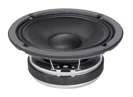
Faital Pro 6FE100
Cheap
5.25 mm Xmax
Rear mounted
Discrete looks
Flat to above 3 kHz
Seas CA18RLY
Not expensive
5 mm Xmax
Discrete looks
Flat to above 2.5 kHz
Seems popular in the diy community

Seas ER18RNX
Slightly expensive
6 mm Xmax
Discrete looks
Flat to above 3.5 kHz


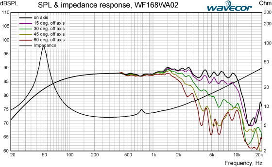
Wavecor WF168WA02
Not expensive
? mm Xmax
Discrete looks
Flat to above 2.5 kHz
Dayton RS180P
Slightly expensive
6 mm Xmax
Slightly aggressive looks
Flat to above 3 kHz

Monacor SPH-170
Not expensive
3 mm Xmax
Discrete looks
Flat to above 3 kHz
Inverted surround should work well for rear mounting
Very positive review in Klang+Ton
Monacor SPH-175HQ
Not expensive
5.5 mm Xmax
Discrete looks
Flat to above 3 kHz
Any one of those that look good for my application?
/Anton
Here are some drivers I've found that look decent.
The only specific parameter that I can think of that is important (when compared to a closed box, and used as mid) is that I want a large Xmax, correct? I would like to be able to rear mount so that a speaker grill (cloth) could be attached directly to the baffle. Intended crossover around 1.5 kHz.
Faital Pro 6FE100
Cheap
5.25 mm Xmax
Rear mounted
Discrete looks
Flat to above 3 kHz
An externally hosted image should be here but it was not working when we last tested it.
Seas CA18RLY
Not expensive
5 mm Xmax
Discrete looks
Flat to above 2.5 kHz
Seems popular in the diy community
An externally hosted image should be here but it was not working when we last tested it.
Seas ER18RNX
Slightly expensive
6 mm Xmax
Discrete looks
Flat to above 3.5 kHz
Wavecor WF168WA02
Not expensive
? mm Xmax
Discrete looks
Flat to above 2.5 kHz
An externally hosted image should be here but it was not working when we last tested it.
Dayton RS180P
Slightly expensive
6 mm Xmax
Slightly aggressive looks
Flat to above 3 kHz
An externally hosted image should be here but it was not working when we last tested it.
Monacor SPH-170
Not expensive
3 mm Xmax
Discrete looks
Flat to above 3 kHz
Inverted surround should work well for rear mounting
Very positive review in Klang+Ton
An externally hosted image should be here but it was not working when we last tested it.
An externally hosted image should be here but it was not working when we last tested it.
Monacor SPH-175HQ
Not expensive
5.5 mm Xmax
Discrete looks
Flat to above 3 kHz
An externally hosted image should be here but it was not working when we last tested it.
An externally hosted image should be here but it was not working when we last tested it.
Any one of those that look good for my application?
/Anton
You lose up to 6 dB per octave due to gradient cancellation. Therefore you'll have to boost lower frequencies. Most hifi drivers require a lot of power to drive them to reasonable excursion in the lower hundreds. Look for pro drivers with a resonance frequency close to the lower end of the bandwidth. Then the driver doesn't draw as much current because of the rising impedance at resonance. Suitable drivers generally have low Mms and low Cms. You don't necessarily require very large xmax, because the volume displacement isn't very large at those frequencies.
Doesn't the excursion increase heavily if I'm boosting the lower frequencies?You lose up to 6 dB per octave due to gradient cancellation. Therefore you'll have to boost lower frequencies. Most hifi drivers require a lot of power to drive them to reasonable excursion in the lower hundreds. Look for pro drivers with a resonance frequency close to the lower end of the bandwidth. Then the driver doesn't draw as much current because of the rising impedance at resonance. Suitable drivers generally have low Mms and low Cms. You don't necessarily require very large xmax, because the volume displacement isn't very large at those frequencies.
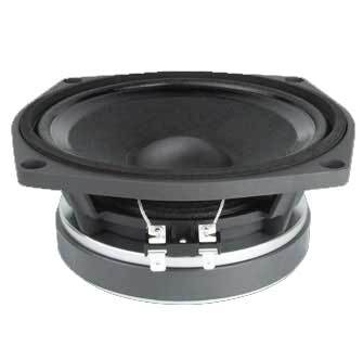
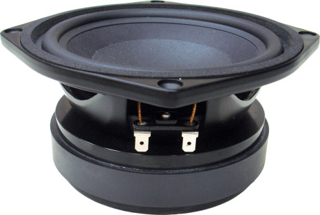
Of the 7 drivers in the last post I'm guessing the Faital Pro 6FE100 was best suited (91 dB sensitivity). How about these:
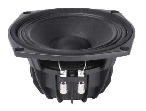
Faital Pro 6FE200
Fs: 120 Hz
Sensitivity: 95 dB (1 W/1 m)
Xmax: 4.67 mm
Rear mountable
Cheap
Slightly jagged response.
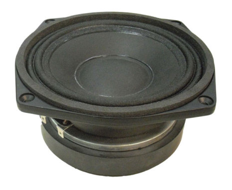
Faital Pro W6N8-120
Fs: 100 Hz
Sensitivity: 95 dB (1 W/1 m)
Xmax: 5 mm
Rear mountable
Sligthly expensive
Not extremely flat, but should be fairly simple to fix with PEQ.
Faital Pro 6PR110
Fs: 100 Hz
Sensitivity: 96 dB (1 W/1 m)
Xmax: 2.75 mm
Rear mountable
Sligthly expensive
No sharp dips.
Beyma 6G40Fe
Fs: 102 Hz
Sensitivity: 94 dB (1 W/1 m)
Xmax: 3.1 mm
Rear mountable
Sligthly expensive
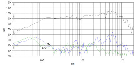
100 dB scale and few datapoints -> I can't really comment on flatness... Slightly troubling dip at 1 kHz.
Beyma 6P200Fe
Fs: 65 Hz
Sensitivity: 93 dB (1 W/1 m)
Xmax: 5.5 mm
Rear mountable
Sligthly expensive
Seems fairly flat.
/Anton
Doesn't the excursion increase heavily if I'm boosting the lower frequencies?
Yes it does. However, unlike at bass frequencies, you are more likely to run into thermal issues before you run in to problems with respect to excursion. Remember that for the same acoustic output excursion doubles for every halving of frequency. At low frequencies you need very little power to get a driver to its xmax. If you want to drive a typical hifi 7" driver to xmax at 100 hertz you might need 150 watts or more.
If your design requires large excursions (think more than about 8 mm p-p), I would advise using 8" drivers instead. You not only get more volume displacement, you also get a greater distance between front and back, for less cancellation.
Never use fiberglass in a vented enclosure.Try filling the enclosure with different amounts of denim(or fiberglass) insulation for better separation down low.
Open the curtains so the sun shines across your speakers and you will see little sparkles on every drum beat
 .
.Dan.
Last edited:
- Status
- This old topic is closed. If you want to reopen this topic, contact a moderator using the "Report Post" button.
- Home
- Loudspeakers
- Multi-Way
- Leaky supercardioid mids