It seems that most on this thread hold the view that an active voltage regulation for the front end of the Leach is definitely an improvement, may it be regular, extended , or the Super.
First objective, as i see it, is coming up with the right regulator for the front of the Leach.
Those who feel for a fully regulated powersupply for the output stage have a good idea by now how much hardware is involved to build an active regulation with a high voltage and current capability, and the high demands on the quality of the active parts.
Seems to me that on DIYaudio the JLH would be the first to try active output regulation on, maybe someone on the JLH thread tried it.
I am a DIY person, not a history teacher or an audio designer.
I received my Toshiba output devices for the Leach, hope to get the Leach boards from Jens in about a week's time.
By then i would be pleased if this thread resulted in the proper voltage regulation circuit for half of the Leach, the front half.
Maybe a good idea to ask Janneman Didden to join this thread ?
Ok then, I suggest we use one of the topologies already suggested on this thread and have someone design us the pcb. If a number of us make a group then we can pay a mark up as well to the designer.
I propose to create this for the small leach amp as for the super one it would be impossible to construct. Any views?
Jens, Jan, Jacco anyone interested in the pcb design?
I propose to create this for the small leach amp as for the super one it would be impossible to construct. Any views?
Jens, Jan, Jacco anyone interested in the pcb design?
As the result of the Super Leach thread is unknow as of today, I would think that I can find the time to do the layout.
Since I will have most of the components in my libs I will create the schematics and a PCB, but the construction and design of the psu I leave to you.
Hows about that?
May I suggest a SKYPE conference?
\Jens
Since I will have most of the components in my libs I will create the schematics and a PCB, but the construction and design of the psu I leave to you.
Hows about that?
May I suggest a SKYPE conference?
\Jens
I would be happy with that arrangement Jens myself. If I ahve a gerber or whatever file that the pcb company can accept I would raise my hat to you...
As regards Skype, I dont have the mic and speakers unfortunately but you have my position on this anyway.
Which regulated PSU design topology will you follow? the more versatile in terms of voltage and current the better.
As regards Skype, I dont have the mic and speakers unfortunately but you have my position on this anyway.
Which regulated PSU design topology will you follow? the more versatile in terms of voltage and current the better.
I would love it if you designed a regulator for the stander leach amp. A think it’s +-57V.
We have two options:
1)
A regulator built with passive (I am using “passive” very loosely) parts (transistors, mosfets, op amps. ect.) The Anthony Holton regulator is a good example.
2)
The other option is a Boosted regulator, A small off the shelf regulator has it’s current capacity lifted. A good example of a low voltage regulator of this type can be seen at http://www.alansmodels.com/links/tom_younger/powersupply.htm
This type of power supply is the type used in the testimonial from Mikett. This type of regulator is simpler to build (fewer parts). I can’t comment on the proforments.
I think I may have the schematic to the one Mikett is talking about. I don’t know what the copy rights on it are, however I can e-mail it to you if you wish.
I am not particularly concerned if PCBs are not available, I have funny heat sinks anyway so they may not be usable anyway.
What is a SKYPE conference?
Leve
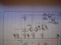
Number two, simple regulator from a fast Elektor amp.
This one is for 70 in, 60 out.
For a higher voltage and current rating :
The BD139 could be swapped for an MJE15030.
The BC546 by MPSA29 or MPSA42, up to 100v in preferably the 29 because it has an Ft of 125 MHz.
3 resistor values altered, and a zener diode.
(could not get a good fix with the light, can scan this one and post a pdf)
Attachments
jacco vermeulen,
The ML looks like only a front and amp, and so totally unsuitable in it’s current form. The other is better. All the regulators you posted all share the same topology more or less. The Anthony Holton regulator also shares this topology. However before we consider any of this we should decide if this is the topology we actually want.
In my post #65 I have split regulators in to two different groups. We must first decide which we like best.
Things to consider:
Which has the lowest Output Impedance. That is based on which is fastest.
Which has the highest noise rejection.
Which is lest likely to go into oscillation.
Jens,
Since you have built it, you’ll be able to decide how much regulation you need based on how much the rails sag.
I don’t what to put words in Jens mouth, but I think we’re going to need about 4 output devices pre rail (MJLxxxxx). With a 10v drop over the regulator and the amp at it’s max draw of 8 amps that’s about 80watts dissipation per rail. With 4 devices its 20watts per device. That seems about right. The 80watts is the peek dissipation however. At idle the amp only draws 200mA at best s the dissipation of the regulator will be only 2watts (4watts for both regulators).
Jens I am dieing to know what your thoughts are. Please do tell.
Leve
Thats funny, the ML pic looks like an active voltage regulator to me.
Even the voltage entries and levels are there, 87 volts in, 65 volts out.
Maybe i am getting old, i even see the regulated and not regulated outputs mentioned on the circuit.
I suppose i am the only one on this thread who desires an active voltage regulator on the front end of the Leach ?
Even the voltage entries and levels are there, 87 volts in, 65 volts out.
Maybe i am getting old, i even see the regulated and not regulated outputs mentioned on the circuit.
I suppose i am the only one on this thread who desires an active voltage regulator on the front end of the Leach ?
But it’s not designed for anywhere near the current we’re talking about. It could only drive the front end. Now that I have looked it up the same is true about the “fast Elektor amp”.
It’s like suggesting that a Childs wheel barrow could transport a 10ton block of steel. Yes it will fit inside, but no it’s not going anywhere.
It’s like suggesting that a Childs wheel barrow could transport a 10ton block of steel. Yes it will fit inside, but no it’s not going anywhere.
Stability
From a stability standpoint, the three terminal device looks to be the easiest and safest. Over the years, every time I hear of a discrete high current regulator, I always hear of instabilites somewhere along the way. That scares the heck out of me with high power amps.
Reliability & Protection
What I can say is that I have built 6 Boak regulators and none of them were unstable. I know of at least 12 more and all have been rock solid with no reliability problems. Furthermore once it actually protected the output section of my amp.
Performance
As for performance, it is NOT the best from a low output impedance standpoint at high frequencies BUT that was in comparison to PSUs driving preamps such as the Sulzer and the Jung/Didden super regulator. I strongly suspect nearly sure that if one of the newer LT three terminal devices were used, it would not be shabby at all especially at low frequencies. Again, taken in perspective, no passive xformer cap arrangement even comes close. Also keep in mind that the LT will pass high current transients and it is this ability that allows the whole arrangement to carry high currents.
Please someone dig out those older TAA in the early 80s. Mine is in storage right now or else I'd offered them up by now.
Banned
Joined 2002
Skype is Voice over ip software for free i bought a head set with a mic and i talk to jen's all the time now, we have it down to a art for when to talk i get up he is getting home from work when i'm coming home from work he is going to work 9 hours difference : O ) Skype is a nice piece of software i recommend it for sure
Mikett said:TAA 1980 Regulated Power Amp Power Supplies
TAA 1983 Measure Power Supply Output Impedance, Pt 1-2
TAA 1981 POOGE-2: Hafler DH-200 Upgrade
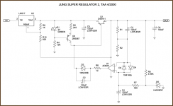
TAA 1995 issue 1,2,3,4, Jung/Didden/Galo, "Super regulators for audio".
Jan Didden
Boaks ?
Could be you wont feel that glad with me on skype, i talk even more than i type.
Maybe this thread needs a head count:
those who want a good one for the front and those who desire something for the back(side).
An integrated voltage regulator circuit i can just do myself, and better than with LT317/337.
I have a couple of tubes of Military versions, in TO3 case, the LT117AK is the MIL spec version of the LT337.
(ex airplane factory stock)
http://tangentsoft.net/elec/opamp-linreg.html
In the 4/2000 issue of Audio Electronics (successor to TAA), Walt Jung published a new version of his regulator with several improvements over the 1995 circuit:
http://tangentsoft.net/elec/misc/diy-series-linregs.pdf
In the 4/2000 issue of Audio Electronics (successor to TAA), Walt Jung published a new version of his regulator with several improvements over the 1995 circuit:
http://tangentsoft.net/elec/misc/diy-series-linregs.pdf
Attachments
- Status
- This old topic is closed. If you want to reopen this topic, contact a moderator using the "Report Post" button.
- Home
- Amplifiers
- Power Supplies
- Leach Super Amp Regulated supply