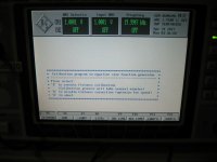
Response is far from flat.
Mark,
I cannot stress enough - you FIRST need to get the generator repaired first, I really fear you are going to cause more damage, EVERYTHING you have posted is symptoms of the blown Gen Output stage.
When the parts arrive from Farnell, replace:-
BD140 / BD139
BC850 / BC860 on the Output Devices Emitter Resistors
All the 3.32 Ohms resistors
Repair the damaged Generator Attenuation resistors - and then I strongly suspect from experience all will be good (as long as your PSU rails are OK)
Mark,
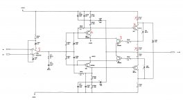
Is N82 the opamp driving the damaged output stage (I'm not sure which channel is damaged)? if so then for sure you will see oscillation as N82 feedback is taken from the output stage.
V84 and V87? (I cannot read the schematic) are the output current sense transistors
Yes, it drives V81 & V85, which drive V82 & V83. V84 (diode) and V87 form what appears to be a feedback loop in the positive half of the amplifier. I could imagine that this circuit would be unstable without the feedback, but unless the feedback continues to the input of the op-amp as well, I have doubts that it would cause the op-amp to oscillate like this. But when the parts come in and I have replaced all failed transistors and resistors, I'll see what happens.
small good news is that you have now "engine running". Much easier to do the fault finding that with completely dead unit.
Meanwhile I try to understand XL600 circuit. Some oddities found immediately like R301 5R PTC between chassis and 0-rail. Also stereo-mono switch shorting other input whwn in bridge mode. Some strange tuning capacitances at Q102 and Q104 gates.
Yes, we're making progress. I assume that the high distortion and poor frequency response flatness are due to the damaged generator, as is the case with the self test failing on many ranges.
The XL600 has power bandwidth to 500KHz, which makes it a good RF amplifier, and thus prone to instability. The designer attempted to mitigate the problem with that 5R PTC in the ground circuit. But the fatal flaw was grounding the jack shields to the chassis and not the power supply ground. I have encountered this problem in two Phase Linear D500's, whose jack shields became grounded after 39-40 years when the anodizing that isolated the jacks from heat sink ground, failed and the amplifier became a power oscillator when powered on. Isolating the jacks cured the problem. As soon as I saw grounded jack shields on the XL600, I knew what the problem was.
")
Mark,
I cannot stress enough - you FIRST need to get the generator repaired first, I really fear you are going to cause more damage, EVERYTHING you have posted is symptoms of the blown Gen Output stage.
When the parts arrive from Farnell, replace:-
BD140 / BD139
BC850 / BC860 on the Output Devices Emitter Resistors
All the 3.32 Ohms resistors
Repair the damaged Generator Attenuation resistors - and then I strongly suspect from experience all will be good (as long as your PSU rails are OK)
Here are the bad components that I've identified from channel 1 (see photo).
Do you think that just having it powered on will cause more damage? Or running tests?
The interesting thing is that the two generator outputs appear to be independent but in actuality, seem not to be independent. The output at the attenuator input of Ch 2 is clean, but the output of Ch 2 at the XLR jack has the exact same RF-pollution as the output of Ch 1.
Attachments
I could imagine that this circuit would be unstable without the feedback, but unless the feedback continues to the input of the op-amp as well, I have doubts that it would cause the op-amp to oscillate like this.
The Opamps feedback DOES include the current boosting OPS, its not operated open loop...
I believe your not seeing the whole schematic, if you look at page 92 of the PDF you can see V1_34541 & V2_34546 represent the concerned 5534 & current buffer OPS, where now you can clearly see the full feedback loop...
all will be good when your repair the damaged Gen Channel Do you think that just having it powered on will cause more damage? Or running tests?
Yes, I VERY MUCH FEAR having the unit powered with damaged parts can cause more damage. You run the risk of overloading the PSU or reverse biasing bootstrap caps etc.
You run the fear of God into me when you fed external power into the unit - with complex multi-rail systems, backing feeding power can cause all kinds of latch up damage... Power sequencing is VERY important to prevent damage in multi-rail systems. NEVER feed external power into a complex system like this unless you understand what is going on and can fully isolate the concerned sections.
This is why I keep repeating please don't explore anymore & just wait for the parts to arrive then repair the damaged Gen section and take it from there.
Last edited:
Replace all the parts marked (but not the opamp), and for good measure (I suspect your having trouble measuring them in circuit) - replace the same parts on the lower section of the circuit (PNP instead of NPN etc).
With an event like this, check the Diodes across the output transistors E/C.
With an event like this, check the Diodes across the output transistors E/C.
I am on that path, JohnW, don't worry!
The reason I backfed power into the supply rails is because the ohmmeter could find no shorted components. It became apparent that whatever the overload was, required voltage above that injected by the meter in order to manifest the fault. The process of 'forcing' power into the bus revealed a fault with V81 and changed the fault with V82 from a threshold short to a real short. It went from reading several thousand ohms to reading 198 ohms. Then I knew for sure those components were the ones holding the rail down.
I'll leave the op-amp alone, unless the oscillation continues with new parts. I should be easy to check the diodes at the E-C junctions with the transistors removed. I can check them with a curve tracer or component tester function on my Fluke 867B.
I'll take your word for it on the feedback loop. Schematics that span this many pages become a major labor to trace signals across. I didn't see a connection between V1_OUT and +IN1 / -IN1. It looks like the output of V1_34541 on pg 92 is connected to the output of the output transistors on page 103. Rather, it looks to me like the inputs of the 5534 are directly coupled to the outputs of N9/10 on pg 101. But regardless, let's see what happens when the transistors and resistors are replaced.
Parts should arrive on Saturday, according to the tracking information on the shipment.
Plan is not to tamper with it until I've rebuilt the output amplifier and attenuator with new parts. If all problems are corrected, then there's no need to further experiment (I hope!)
Plan is not to tamper with it until I've rebuilt the output amplifier and attenuator with new parts. If all problems are corrected, then there's no need to further experiment (I hope!)
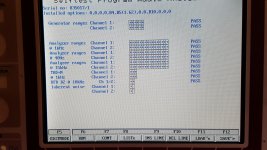
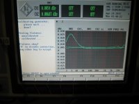
I finished rebuilding the output circuitry replacing resistors in the amplifier stage and in the attenuator. It passes self test!.
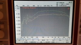
The only concern is his this frequency response to non flat? I don't remember it being quite this out of whack.
The only concern is his this frequency response to non flat? I don't remember it being quite this out of whack.
Attachments
Congratulations on getting it running again.
Those level variations are in the mud. The instrument is not really able to show that level of accuracy even if it has the resolution. You need a thermal converter to verify its flatness like one of these: Standard Voltage Thermal Converter, Low Voltage Thermal Converter, Improved Accuracy Thermal Converter . But its way beyond any performance limitations in the real world. I have a 600 Ohm converter if you really want to obsess. I believe you have better projects to pursue.
Those level variations are in the mud. The instrument is not really able to show that level of accuracy even if it has the resolution. You need a thermal converter to verify its flatness like one of these: Standard Voltage Thermal Converter, Low Voltage Thermal Converter, Improved Accuracy Thermal Converter . But its way beyond any performance limitations in the real world. I have a 600 Ohm converter if you really want to obsess. I believe you have better projects to pursue.
I finished rebuilding the output circuitry replacing resistors in the amplifier stage and in the attenuator. It passes self test!.
The only concern is his this frequency response to non flat? I don't remember it being quite this out of whack.
Great!!! - told you so
, similar's happened to a couple of UPD's in my lab over the years..Oh - Wait, damn, I guess you will not be swapping for the AP now
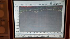
Frequency response looks fine, its in the 0.001dB range that impressive...
UPL response cal
Looks promising.
Have you done the user calibration described in the user manual:
2.6.9 Improving the Frequency Response
The analyzer of the UPL is generally equipped with a frequency response calibration for rms
measurements which compensates for the systematic frequency response errors of the internal
components. To activate the calibration it is required that the frequency measurement is switched on
with rms measurements or "Meas Time" set to GEN TRACK.
If – for measurements with built-in universal generator - the frequency response is to be further
improved, the remaining frequency response of the analyzer in conjunction with the generator frequency
response can be smoothed additionally by means of an instrument-specific equalization file.
To create this equalization file ("FLAT_GEN.CAL" under C:\UPL\REF), a BASIC program
FLAT_GEN.BAS is supplied on the "SETUP/EXAMPLES" disk and loaded into the directory
"C:\UPL\USER" with installation. It may be started as a macro, if the UPL-B10 option is installed. The
equalization file can also be created manually using the "FLAT_GEN.SAC" setup. .............
Attachments
It was a tour de force in SMD soldering, I can tell you that! I never soldered so many SMD parts in one repair before! But I've gotten a LOT better at it since replacing a small RF chip transistor in a Moseley microwave STL some years ago.
The next challenge is to incorporate some protection to my cabling to the UPL that will limit common mode current to a microscopic level, just in case another huge power amp goes berserk.
I went over to Ken Rockwell's UPL page and compared to his generator flatness tests, so I'm convinced all is well with mine.
Yeah, sorry, I'm keeping my UPL.
Looks promising.
Have you done the user calibration described in the user manual:
2.6.9 Improving the Frequency Response
.............
Yes, I ran that macro. The question is, is it persistent, or does it have to be run every startup?
What I understand from the user manual is:
As long as you have FLAT_GEN.CAL file at C:\UPL\REF folder UPL uses it. In certain situations whwn you do not to want to use flatness cal you can rename, remove or disable the file with FLAT_GEN.BAS utility.
Okay so the option to make it a persistent calibration is there. That's good. I'll have to check and see where that Cal file is located.
- Status
- This old topic is closed. If you want to reopen this topic, contact a moderator using the "Report Post" button.
- Home
- Design & Build
- Equipment & Tools
- LCD Backlight for Rohde & Schwarz UPL?