Re: Ripple in still water, when there is no pebble tossed
Good reverse-thought-engineering Fred.")
Perfect example on how an innocent little correct explanation can get blown out of proportion in the the wrong hands.
Fred Dieckmann said:I believe that the point the guy explaining this to Lars was trying to make is that if attention is not paid to PCB and wiring impedance, the caps can very well have different ripple currents across them. One of the reasons for using multiple capacitors that each individual capacitor is not rated to carry a disproportionate share of the ripple current and that the ripple current is to be divided equally by the number of caps in parallel. This prolongs the life of the capacitors and is just good engineering. I have a feeling that it was the in the context of wiring and PCB impedances that this was presented.
Good reverse-thought-engineering Fred.
Perfect example on how an innocent little correct explanation can get blown out of proportion in the the wrong hands.
Adding to what Fred just posted, you may have a look at the
two schematics I posted earlier in this thread. Seems like nobody
paid attention to them, being more interested in burgers and
the etymology of "whopper". I don't know if those solutions are
approved as good enough by Fred, though, and they are only
part of the solution, of course. Resistors between bridges and
caps etc. still useful, as also Fred pointed out.
A sweep test like this can give you a good qualitative assessment of a capacitor's sonic performance. Even in just one single capacitor there are large amounts of resonances, also in the audioband. With several caps in parallel, the resonances explode.
Another thing: A Black Gate VK has much lower resonances than a normal paper electrolytic cap. And sounds better too.
(Note the graphic below is drawn for illustrative purposes, not an actual measurement).
Another thing: A Black Gate VK has much lower resonances than a normal paper electrolytic cap. And sounds better too.
(Note the graphic below is drawn for illustrative purposes, not an actual measurement).
Attachments
Capacitors............
Lets get down to nitty gritty..........what is the best approach
sonically......................that won't be hugely expensive..............
most Aleph-X amps will probably be arround 100watt ..............
so typically what should be aimed for.............
so far it seems keep capacitors to highest quality but least number to do job.
use 2 rectifiers
D3 Bolton uk
I think this has been a useful thread. Thanks Claus!
Another point which has not been adressed is the fact that as you increase the capacitance of your PSU, you also significantly increase the current spikes in transformers and diodes while shortening the pulses. Some resistance will re-lengthen the pulses. Unless pulses are lenghtened, you need progressively bigger transformers to deliver the required current for the shorter pulses.
I have moved over to switched mode for these and other reasons.
Petter
"These curves should speak for themselves."
I guess they will have to with no scales or explanation. I have no idea of what I am looking at. Tell us the test conditions and the range and units of the X and Y graph axis. Volts? dBm? Hz? furlongs per fortnight? What exactly are we looking at.....
I guess they will have to with no scales or explanation. I have no idea of what I am looking at. Tell us the test conditions and the range and units of the X and Y graph axis. Volts? dBm? Hz? furlongs per fortnight? What exactly are we looking at.....
Resonance?????
I don't see no stinking resonances.
Next time, try measuring the magnitude AND phase of the DUT, and showing the results in a polar plot.
And it might help to put a DC bias on a polarised cap.
What you claim to be a resonance on your drawing looks like noise, and the plots are not any more convincing. What exactly is is trying to illustrate?
I trust that you will have it sorted out by the time I return. I don't want to have to 'splain this again.
Yes, all caps have a self-resonant frequency, but this does not seem to be what you are trying to porve.
Jocko
Fred Dieckmann said:"These curves should speak for themselves."
I guess they will have to with no scales or explanation. I have no idea of what I am looking at. Tell us the test conditions and the range and units of the X and Y graph axis. Volts? dBm? Hz? furlongs per fortnight? What exactly are we looking at.....
Dammit, Fred, you beat me to it.
Hi,
Looks like a Caterham Lotus Super Seven to me but I don't think it's Jocko driving it...
Cheers,
Is that you in a Lotus Super 7?
Looks like a Caterham Lotus Super Seven to me but I don't think it's Jocko driving it...
Cheers,
Lars Clausen said:Interesting reaction pattern ..
Why? If you post diagrams with no explanation of what is
plotted you should expect people not to understand. I am
as puzzled as Fred, SY and probably everybody else. The
only interesting reaction is from Jocko, who seems to have
managed to decipher something out of the diagrams, despite
the lack of info. Maybe he has used the same software/equipment
as you, so he knows what to read out from the terribly
messy texts.
Christer: My remark about 'Interesting Reaction Pattern' is related to the fact that a few guys in here have the habit of changing the subject towards Hamburgers, yellow cars or whatever, when they can't think of something better to say.
My point is that capacitors have resonances, and paralleling capacitors directly will allow these resonances to increase significantly. The resonances are interactions of one capacitors's capacitive part with other's inductive parts, or what i have called Current Woppling. Maybe somebody dislike this word, and certainly some people in here also dislike the effect all together. But it's there, even for the people who are in denial of either its existance or significance.
So presenting evidence that my claim of current woppling is NOT 'mostly crap', as someone in this thread want to impress.
I must admit that 10 years ago i was out there promoting to parallel a number of smaller caps instead of using one big one.
A bunch of people from Scandinavia who are reading this thread can probably remember this.
But the people from Chemi Con (former Sprague) made me aware that maybe parallelling directly wasn't the best solution after all. A better way should be found. So we did the Virtual 4 Pole setup, where capacitor interaction is prevented by controlling the capacitor interaction with small resistances.
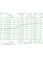
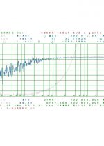
Now to an explanation of the curves:
The BLUE curve is the phase of the capacitor, 0deg. in the bottom, 180 deg. in the top, 36 deg. per div.
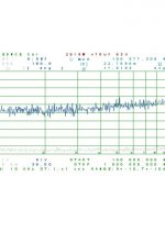
The GREY curve is the impedance 0 Ohm at the bottom, 1 Ohm at the top. The frequency span of this measurement is from 100 Hz to 5.000.000 Hz except for the 'normal 470uF cap' it spans in a higher resolution from 100.000 Hz to 1.000.000 Hz i'm sorry i don't have the same freq. span for that one like the other two. But i think the resonances are obvious just the same.
Anybody who is reading this thread can repeat the impedance part of this measurement using the simple setup presented earlier in the thread, and see for himself whether my claims concerning current woppling hold up or not.
My point is that capacitors have resonances, and paralleling capacitors directly will allow these resonances to increase significantly. The resonances are interactions of one capacitors's capacitive part with other's inductive parts, or what i have called Current Woppling. Maybe somebody dislike this word, and certainly some people in here also dislike the effect all together. But it's there, even for the people who are in denial of either its existance or significance.
So presenting evidence that my claim of current woppling is NOT 'mostly crap', as someone in this thread want to impress.
I must admit that 10 years ago i was out there promoting to parallel a number of smaller caps instead of using one big one.
A bunch of people from Scandinavia who are reading this thread can probably remember this.
But the people from Chemi Con (former Sprague) made me aware that maybe parallelling directly wasn't the best solution after all. A better way should be found. So we did the Virtual 4 Pole setup, where capacitor interaction is prevented by controlling the capacitor interaction with small resistances.
Now to an explanation of the curves:
The BLUE curve is the phase of the capacitor, 0deg. in the bottom, 180 deg. in the top, 36 deg. per div.
The GREY curve is the impedance 0 Ohm at the bottom, 1 Ohm at the top. The frequency span of this measurement is from 100 Hz to 5.000.000 Hz except for the 'normal 470uF cap' it spans in a higher resolution from 100.000 Hz to 1.000.000 Hz i'm sorry i don't have the same freq. span for that one like the other two. But i think the resonances are obvious just the same.
Anybody who is reading this thread can repeat the impedance part of this measurement using the simple setup presented earlier in the thread, and see for himself whether my claims concerning current woppling hold up or not.
I see the series inductance of two of the test caps (at RF frequencies), but other than that, I don't see any "resonances" there, just baseline noise. The "normal" cap shows zip below a megahertz, other than the same pretty random looking baseline noise. Could you explain to me what I'm missing?
Lars Clausen said:SY: Well maybe your 'Random Noise' is not just hiss from the input amplifier. Maybe it reveals that the capacitor has shifting phase response at shifting frequencies. In other words : Resonances.
Lars,
I hate to say it, but that looks like noise to me too. I've measured the impedance of capacitors from audio frequencies, to several gigahertz all kinds. Any time I got a measurement like that it was either due to:
1. The impedance was too low for the meter to accurately measure. (Not paying attention to the dyanmic range of the instrument.)
2. The impedance was too high for the meter to accurately measure. (Not paying attention to the dyanmic range of the instrument.)
3. Bad connection.
4. Noisy signal generator.
Without knowing the makes, models and wiring of all of the instruments/dut in the test then it's hard to gain anything from the caps you posted.
Scott
- Status
- This old topic is closed. If you want to reopen this topic, contact a moderator using the "Report Post" button.
- Home
- Amplifiers
- Pass Labs
- LC Audio story on current woppling?