Hi Jostwid,
Bias current for the 2SK82 is miniscule - in the order of microamps. There is really no need for a separate transformer/full wave rectified source - NP's B+ derived solution which I attached, is more than up to the job and I suspect much superior with regard to time constants etc. However please don't let me discourage you from your pursuit, we might all learn from your efforts. Whatever you do just carefully monitor the drain/source current on power-up. In my case, I was sufficiently alarmed to feel the need to include the .33 ohm source resistor. If you feel the need to regulate, use the adjustable LM337 or better still, its higher spec equivalent - IMHO the 2SK82 deserves better than a 79xx.
Antoinel - It's been a while since I saved NP's circuit as a Jpeg - I have no notes nor do I remember where it was downloaded from - sorry.
My apology for the confusion which audiong cleared up [thank you] in the preceeding post. He referred to Mr. Pass as The Master, and attributed the bias tracking circuit to him.I don't know what you're talking about.
Ah, well no worries anyway, Antoinel. I was trying to have a little fun with audiong, but that sort of thing doesn't always go over without lot's of smilies and grins. ")
As for regulated bias, I have a meter on the Vds of my inductor L'Amps. (Amps which have played reliably for hundreds and hundreds of hours now) It doesn't move. The distortion meter doesn't move either.
I don't think it's quite the horror everyone imagines in their thought experiments, but of course you're free to regulate everything or nothing as you see fit.
I am glad you had fun. Thanks for the comforting tech info regarding SIT bias. Experience talks. Best regards.Ah, well no worries anyway, Antoinel. I was trying to have a little fun with audiong, but that sort of thing doesn't always go over without lot's of smilies and grins.
As for regulated bias, I have a meter on the Vds of my inductor L'Amps. (Amps which have played reliably for hundreds and hundreds of hours now) It doesn't move. The distortion meter doesn't move either.
I don't think it's quite the horror everyone imagines in their thought experiments, but of course you're free to regulate everything or nothing as you see fit.
Bias supply
To Michael: It is nice when you live in an environment with stable mains supply.
To audiong: Your proposal is of course much more elegant and propably also more responsive to changes and might contribute to more benign clipping????
I had not been aware of this circuit prior to your posting. And i had no better to propose than the second transformer.
Nevertheless i shall try it (it is 8$ investment..) To have galvanic separation from the B+ might have some other advantages, like less pollution to find its way towards the gate.
Hello SIT people...)
I have made a test today whit fixed bias instead of auto and found
that if you use unregulated psu, there is no way to use fixed bias.
I got 1.1A max whit fixed on 12.4V battery and whit autobias avarage 12.5V (min12.2-12.6Vmax) 0.715-0,82A at 63V. So I cant use fixed, too much diference.
Unbypassed also is not an option, the Rp will go up and I would need more inductance...What do you think about high power LEDs 3-4 in series???
The problem is whit unbypassed resistor I get high output impedance...I calculated 92ohms. (Rp+(mu+1)*Rk
This is no problem whit my output transformer I could use the 500R primary but I also had to change the plate reactor to
5-6H at 800mA, thats more expensive...) Or A CCS?
Last edited:
Good evening,
a dumb question: can I use the scheme as per figure n.11 but with a 100mH inductor instead ot the bulbs and with a 18v transformer for the psu?
Thank you
You should be able to, as long as the inductor has low DCR. The 193V version has a 150 mH inductor of 1 ohm at 24V and Michael discussed a lower power version with slightly lower voltage.
You should be able to, as long as the inductor has low DCR. The 193V version has a 150 mH inductor of 1 ohm at 24V and Michael discussed a lower power version with slightly lower voltage.
Thank you.
Hope to be able to build it soon, my choke is a double 100mH + 100mH rated 4A each, with low DCR (I think around 0.89 ohm), and I also have a 400VA toroid transformer 18v + 18v to put in use!
I liked the scheme without negative p.s. for the bias because it's simpler, and my transformer is suitable for the low B+ of the 193v Hammond version.
I'm also curious to build the "power buffer" version, if I only could understand which choke to use (crossover ones?).
So many amps, so little time!
Ciao!
If you have an 18v trafo then it will become roughly 24V in the amp =) You could probably follow the top part this schematic since your inductor spec is almost identical to the 193V and with the lower part of fig 11, so 1 ohm source resistor and so since if I've understood correctly you won't use negative bias. Though to be safe you should use 10K instead of 47K for the parallell resistor if I remember correctly.
Last edited:
After much procrastination and building on other things I've finally assembled enough to test this little amp, and if it works assemble the last on the other channel too.
My questions are the following: What should be done first is to verify that the bias is ~ -12V to ensure that the SIT doesn't break?
And another question about 2sk82 grades: The KD-33 grades work in the positive biased version but do they also work in the no degeneration bias supply version? I currently have KD-33 grades but if I like this amp I'll probably buy another set of 2sk82s in case I do something dumb and break one. The only grades left on circuitdiy is KF-33 and KD-33.
If the KD-33 works in the bias supply version in addition to the single supply version then I know which grade to stockpile =)
Last edited:
It's alive... it's alive! muhahahahaha!
I guess it worked after all =) I'll have to assemble the last on the other channel too since I'm waiting for the crossover parts to the speaker anyway.
Currently it's 2A @ 20V, I have yet to hook up the scope and fine tune the distortion profile.
I guess it worked after all =) I'll have to assemble the last on the other channel too since I'm waiting for the crossover parts to the speaker anyway.
Currently it's 2A @ 20V, I have yet to hook up the scope and fine tune the distortion profile.
Attachments
Hmm... I'm thinking if I should assemble the other channel into an inducted F2J first and compare it to the L'amp first before I go all out on the SITs. The F2J has so nice output impedance when used without the parallel resistors =)
Who knows, I might enjoy the F2J more but I might not... and then at least I'll know what I prefer =)
Who knows, I might enjoy the F2J more but I might not... and then at least I'll know what I prefer =)
I've trimmed the pot some each way to dial in distortion but I don't get any significant change by small trimming. I think I'll just keep it at 2A @ 22V, stop worrying and just enjoy the sound =)
And maximum power is ~ 9V RMS into 9.4 ohm so sounds about comparable with 10W into 8 ohm. And the 193V does ring... when you apply large sinewaves at several watts but it's quiet at 1W even with a pure 1khz sine wave so I'm not worried about that anymore
It doesn't have a lot of gain, about 6 dB since I use a Jensen JT-11P-1 to convert from balanced to single ended but with my 5V RMS capable source it seems to be enough.
Last edited:
More Bias...
Hi audiong,
As promised in #1955 i finally tried the bias tracking with the bias transformer coupled to the main.
With regard to tracking tracking it is ok.
The problem was the unexpectedly high inrush current at switch on. It was 3x the nominal current with an inductor DCR 3.5 Ohm and a lot more with the inductor i normally use that has 0.4 Ohms.
I shall use a B+ delay to mediate.
Hi Jostwid,
Bias current for the 2SK82 is miniscule - in the order of microamps. There is really no need for a separate transformer/full wave rectified source - NP's B+ derived solution which I attached, is more than up to the job and I suspect much superior with regard to time constants etc. However please don't let me discourage you from your pursuit, we might all learn from your efforts. Whatever you do just carefully monitor the drain/source current on power-up. In my case, I was sufficiently alarmed to feel the need to include the .33 ohm source resistor. If you feel the need to regulate, use the adjustable LM337 or better still, its higher spec equivalent - IMHO the 2SK82 deserves better than a 79xx.
Antoinel - It's been a while since I saved NP's circuit as a Jpeg - I have no notes nor do I remember where it was downloaded from - sorry.
Hi audiong,
As promised in #1955 i finally tried the bias tracking with the bias transformer coupled to the main.
With regard to tracking tracking it is ok.
The problem was the unexpectedly high inrush current at switch on. It was 3x the nominal current with an inductor DCR 3.5 Ohm and a lot more with the inductor i normally use that has 0.4 Ohms.
I shall use a B+ delay to mediate.
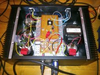
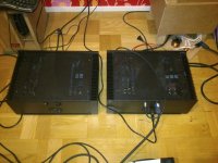
Wiiiie, the next amp is now also done and both work =)
The amp has even moved into the speaker... now I just need to wait for the shipping of the crossover parts. The L'amp is to drive the 6.5" midrange and the tweeters, the woofer and subs are driven by a hypex plate amp.
The speaker is lacking the magic efficiency booster though ( a wool baffle ), but it'll be there in the not too far future =)
Attachments
Wiiiie, the next amp is now also done and both work =)
The amp has even moved into the speaker... now I just need to wait for the shipping of the crossover parts. The L'amp is to drive the 6.5" midrange and the tweeters, the woofer and subs are driven by a hypex plate amp.
The speaker is lacking the magic efficiency booster though ( a wool baffle ), but it'll be there in the not too far future =)
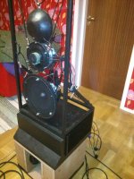
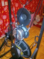
Loooks very promising...I like that gong like tweeter...
Hi Jostwid,
Glad to hear your bias tracking design works well and that you recognize the need to address the switch on current surge. Although there is anecdotal evidence to suggest that the 2SK82 is quite a robust device able to withstand quite a bit of punishment, I do not see that as an excuse nor do I think it advisable, to subject the device to repeated high current switch-on surges in fixed bias configurations.
The power follower design however, side steps the problem entirely - the device ramps up nice and slow almost like an indirectly heated rectifier tube.
Loooks very promising...I like that gong like tweeter...
It's just the rounded backside of a waveguided tweeter
The rear dispersion of the midrange falls off much earlier than the front one so I've helped somewhat with waveguide loading. The crossover is assymetric also with lower crossing on the rear.
Attachments
- Home
- Amplifiers
- Pass Labs
- L'Amp: A simple SIT Amp