If you use an effective CCS you may find that equalizing the currents through the differential amplifier is not needed.
I usually use a pair of devices wired in series, with the top gate referenced to ground via a zener diode, and the bottom gate tied to -V with the source. A biasing resistor is needed for the zener diode, and a second biasing resistor in the source circuit of the bottom device to set the current.
You should see measurably better bandwidth, lower distortion and greater gain with this setup.
I have 2 spare 400VA transformers, but they are 2 x 22VAC, not 18VAC. Can I still use them to build 193V version? Any adjustments need to be made to the original schematic?
Easiest way to drop the voltage would be adding a few more resistors at CRC filter.
4V more is nothing to worry about
just set output node higher, accordingly
What do you mean? Should I set bias a bit lower than 2A?
I suppose I can always drop a couple of volts by adding another RC in power supply filter...
output node means point where output cap is connected ...... I'm pointing on drain voltage practically
you have more than enough info in thread , regarding Iq and output node voltage
what I was saying is - go ahead with your xformers , rail voltage isn't carved in stone
you have more than enough info in thread , regarding Iq and output node voltage
what I was saying is - go ahead with your xformers , rail voltage isn't carved in stone
Hi MaxDear all,
L' Amp style amps, while being wonderful, may be seen (at least I see) as starting points in the learning experience and I cannot avoid wondering about many experiments to be done, like CCS, cascoded CCS, cascoded VFET, which are some of the steps to add to my already modded amp.
I have been using my Tokin amp with a differential amplifier for the input and it really improved a lot.
As some may know, I am experimenting with Peufeu's recommendations for diminishing (putative) thermal memory distortion effects, like the cascoded-CFP input pair. Well, yesterday I replaced the input pair differential with a "cascoded-compound CFP" pair of units, using Toshiba's SK170 as both, the cascodying element and as the "driver" of the CFP pair and a BC560 PNP as the "emitter follower" of the pair, with a 1K resistance on its emitter. I confess I studied some academic articles about this compound Szicklai but they were too much for me, so I took the plunge as the good Lord seemed to advice me...and it worked!
First listening tests are very encouraging.
I attach picture of the cascode-compound CFP units and a diagram of the target amp...
I hope you like it.
M.
Also me have a pair of sk180 as a soon experiment with l'Amp.
For now i have build a pair of MoFo monoblock....very great amplifier.
Waths is the gain of your interesting CFP?
Waths bias have the sk180 for 50v B+?
Hi Max
Also me have a pair of sk180 as a soon experiment with l'Amp.
For now i have build a pair of MoFo monoblock....very great amplifier.
Waths is the gain of your interesting CFP?
Waths bias have the sk180 for 50v B+?
Hi and thanks for your interest.
I now realize that I never posted the updated schematics...I will do ASAP. My AMNESIS amp project is consuming all my free time
 My whim was to put there a CFPcascoded-CFP output and now I my trying to stabilize it That amp rivals this one soundwise...
No idea what the gain might be; I confess I didn't measure much parameters and went directly to listening. The gain is formidable though as both stages amplify. The gain can be set by trimming R1 and R2 on the diffamp, well and also trimming Rd on the output stage.
IMHO, key to good sound is providing separate regulated supplies for each section. I might test now separating signal and power ground with 10R, now that I think of it...
The bias is -3.3VDC for my 180 units and that for 1Amp current, last time I checked...
Mr Pass published a version with CCS that of course must be more efficient. I have it here somewhere...
As I said before, I had not the time to do the multiple mods that swarm in my head
Cheers,
M.
Hi MaxFrom memory...
It is a good idea to put some pins (like from DIP8 adaptors) on PCB to play a little with R values.
thanks for the schematic.
your CFP scheme fascinates me and I would like to try to adopt it as a front-end of the MoFo. since you've posted the diagram from memory I'd like to ask you to verify it.
I could make it fast on a perfboard with a supply at + 15v / -15v.
I would also like it if you describe in detail the most important parts of the circuit and possibly how it works
Thanks again.
Be aware that I'm only a dilletante with no formal tuition in electronics, and that I don't know MoFo nor its requirements from input signal point of view...
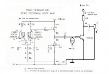
The diffamp is a classic differential amplifier with a common-drain buffer attached. I suppose C1 is not strictly necessary if you have something like C2.
Better go with +/-24 supplies for better headroom. Use your favorite low power VReg.
R1-R2 decide the gain and the resistor tail (R5->Rn) defines the current for the CCS. You must check with oscilloscope to avoid clipping and to secure adequate gain for your next stage. Choose high quality, low noise resistors for best sound. IF you cannot have desired gain, you can mod it with the transistor based mods recommended above.
Note and respect pin description (G.S.D.) for the JFETs as there is a small mistake on the original schematics that I always forget to correct...
Good luck and may the Force be with you.
M
Molti auguri
Be aware that I'm only a dilletante with no formal tuition in electronics, and that I don't know MoFo nor its requirements from input signal point of view...
The diffamp is a classic differential amplifier with a common-drain buffer attached. I suppose C1 is not strictly necessary if you have something like C2.
Better go with +/-24 supplies for better headroom. Use your favorite low power VReg.
R1-R2 decide the gain and the resistor tail (R5->Rn) defines the current for the CCS. You must check with oscilloscope to avoid clipping and to secure adequate gain for your next stage. Choose high quality, low noise resistors for best sound. IF you cannot have desired gain, you can mod it with the transistor based mods recommended above.
Note and respect pin description (G.S.D.) for the JFETs as there is a small mistake on the original schematics that I always forget to correct...
Good luck and may the Force be with you.
M
Molti auguri
many thanks MaxThanks again.
...................................................................
Be aware that I'm only a dilletante with no formal tuition in electronics, and that I don't know MoFo nor its requirements from input signal point of view...
M
Molti auguri
Has anyone tried using the 193u? I searched for 193u and didn't get any results. It is 200mh with 2A rating. 1.7ohm resistance though. Would it work on the self biased version @1.6A, or is the resistance too high?
Thanks
You need to increased B+ for self bias, use 2x25V transformer
HI Max,
Mike Rothacher suggested this...
*--------------------------------------------------
*2SK180
*GENERATED BY SIT MODELER @ AUDIOHOBBY.COM
*MODEL RANGE: 100V, 5A
*--------------------------------------------------
.SUBCKT 2SK180 D G S ; Drain Gate Source
+ PARAMS: MU=17 X=1.5 K=0.67 N=1.76 VCT=0 RG=2MEG
*--------------------------------------------------
B1 D S I=K*PWR(URAMP((V(G,S)+VCT)+(N*LN(V(D,S))+(V(D,S)/MU))),X)
*FOR MULTISIM COMMENT OUT ABOVE LINE (*) AND UNCOMMENT NEXT LINE
*B1 D S I=K*PWR(MAX((V(G,S)+VCT)+(N*LN(V(D,S))+(V(D,S)/MU)),0),X)
R1 G S {RG}
CGS G S 2000P
CGD G D 2000P
CDS G S 0P
.ENDS 2SK180
*--------------------------------------------------
HI Max,
Mike Rothacher suggested this...
*--------------------------------------------------
Great! Thanks.
I'll see if it works for me...
Best wishes,
M.
- Home
- Amplifiers
- Pass Labs
- L'Amp: A simple SIT Amp