Of course, l12-2 is not a perfect amplifier.Ok , understood.
this is good.
I've been thinking about how to make it better.
Such as canceling the input capacitor. Use a copper wire instead.
The voltage amplification stage also adopts the coascode structure. Thus, bc550c can be used as a voltage amplifier.
Is that a problem?I've been thinking about how to make it better.
Such as canceling the input capacitor. Use a copper wire instead.
please:
Attachments
This is not the circuit I designed.Is that a problem?
please:
This is the wrong design.
where is that diagram?This is not the circuit I designed.
This is the wrong design.
Do you want to do something differently in this topology without a capacitor? try...
The circuit is very simple. You can find many error free ones on this forum.Do you want to do something differently in this topology without a capacitor? try...
I don't quite understand what you mean by doing other things without capacitors.
In fact, I don't think the making of amplifiers is a question. It is more like a multiple-choice question.
Because it has many, many solutions, or answers.
Many of these answers are not correct or wrong.
It is a choice. Maybe we didn't choose the best one. But it's good not to choose the wrong solution.
In fact, I made a lot of new things in the experiment. But in the end, I gave up these plans.
Because many things have not been verified by time.
it is logical that there are many schemes and there are no solutions, probably because the schemes are very simple ...In fact, I don't think the making of amplifiers is a question. It is more like a multiple-choice question.
Because it has many, many solutions, or answers.
Many of these answers are not correct or wrong.
ok, we are waiting for the time to check, and I will go about my business ...Because many things have not been verified by time.
Are you asking me. I'm sorry I can't always see people asking questions.Can you tell me more about an RC network connecting LTP collectors? It doesn't look like a regular Miller compensation. I've seen it before in some schematics but I've never heard an explanation.
Because I didn't know anyone was asking.
Besides, my English is poor. Some professional explanations could not be explained in detail.
But I like to make one thing simple.
For example, the principle of RC is to pass some frequency signals.
Because RC is small. The passing signal frequency is relatively high. Low frequency cannot pass.
We can express this by many different nouns. But the principle is the same.
In fact, in an amplifier. It is not recommended to have too many RC filters.
It makes the signal in the signal. Attenuation. Or disappear.
Unless there must be some redundant signals, the amplifier will be unstable. There is a problem. Well, at this time
We need to join RC.
But in a stable amplifier. Add extra RC. The thd becomes worse.
Because it will lose some signals. Because the RC filter is not a fixed frequency.
Because it is diagonal- 3dB. Even a small part of the signal in the audio may be lost.
Can you tell me more about an RC network connecting LTP collectors?
this RC correction circuit is placed at highohm points in case the diff cascade works with a paraphase signal, its task is to symmetrical the diff cascade operation at higher frequencies, because capacitance with increasing frequency is a shunt. If you have an axial(single) driver, this RC circuit is either connected to the common point of the next stage or to GND.
No, this is an element of progressive correction and has nothing to do with Miller, because the time constant of this circuit does not depend on the gain of the cascade where it is installed.It doesn't look like a regular Miller compensation.
This is actually a problem, because many designers put such a chain without even understanding its purpose ...I've seen it before in some schematics but I've never heard an explanation.
With simulation, this scheme is a form of frequency compensation in the amps loop gain. It somehow effectively controls/flattens an appearing bump shown in ac transient analysis of the closed loop gain. It will also reflect in the square wave test by removing overshoots and or ringing. This scheme resembles the RC network also attached in the collectors of VAS and its current source. (collector and emitter of vbe actually). Another form of feedback compensation. I guess this scheme is now being replaced by TMC/TPC. It may look crude and perhaps an old technique? 🤔Can you tell me more about an RC network connecting LTP collectors? It doesn't look like a regular Miller compensation. I've seen it before in some schematics but I've never heard an explanation.
But if it works well then it must be good, (?) I had it in my current design experimentation.
http://calvins-audio-page.jimdo.com/Hello,
Anybody here can point me to Calvin's website? I've PM'd him but got no replies till now..
( I am actually looking for the .asc file for LJM-L12).
Regards,
Albert
Hello,
Anybody here can point me to Calvin's website? I've PM'd him but got no replies till now..
( I am actually looking for the .asc file for LJM-L12).
Regards,
Albert
Calvin has replied, I received the files that I'm looking for.
Thanks!
Albert
(Sorry ljm if my posting goes O.T.)
Dear ljm, I recently purchased this amplifier board on Ali. I've experienced it for myself. It turned out that this amplifier really has a great sound and good characteristics. Good average level. But, unfortunately, this is far from the parameters stated on the seller's website. After the test, I realized that the quiescent current is very small and in order to achieve the stated characteristics, it is necessary to increase the quiescent current..
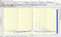
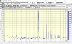
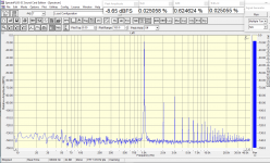
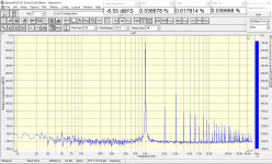
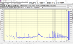
The measurements were carried out with a bipolar power supply = 30 V, at a load of 8 ohms and an output power of 1; 10; 20; 30 and 45 Watts, the pictures are listed in order.
Unfortunately, I didn't see any similar measurements here in this program, which is a pity. Could you make similar measurements so that I can compare the results. Here is the address of the site where detailed information is provided: https://aliexpress.ru/item/40010154...74.530824031.1663865534-1031465528.1663612562
The quiescent current of this board = 16.5 mA, which is very small. This is more in line with class B. Then, I began to look for distortions of the "step". These distortions appeared very well at 100 kHz and very weakly at 20 kHz. And it became clear that it was necessary to increase the quiescent current.
Last edited:
I might do that, just I have to take the board from the bin where it ended after testing it. The results were similar to yours, not so convincing, far worse than the values declared by the seller.Could you make similar measurements so that I can compare the results.
There were many "sounds great" statemens here, but I'm afraid the positive reviews were greatly affected by the misleading graphs provided by the seller. Placebo effect.
By the way, test the board for square vawe response at lower frequencies and for stability. If not properly grounded, the board can burst into wild oscillations and then burn the output devices. I would never test this on speakers without good speaker protection. Its risky.
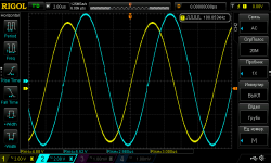
Dear Berlusconi, after a long experience of shopping on Ali, I do not trust sellers, but sometimes I come across masterpieces. This board is not a masterpiece, but of a good level. Before connecting the speaker to it, I warmed it up for several hours and tested it on a powerful load = 8 ohms. Thank you for the warning, but there were no surprises during the testing process. Although I subjected her to quite serious tests. And yes, when connecting a new amplifier, I use protection for the speaker. Here is one of the tests.
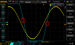
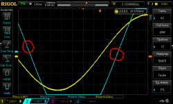
Clip and signal strength before the clip. I also checked the rectangle, but the rectangle on the HF, I really don't like it! Low cutoff frequency! I would reduce the input filter capacitor.
Clip and signal strength before the clip. I also checked the rectangle, but the rectangle on the HF, I really don't like it! Low cutoff frequency! I would reduce the input filter capacitor.
Attachments
I'll tell you about nutrition. This board was tested when powered from a laboratory source. It has a very small level of its own noise. Later I will make graphs, with an unstabilized power supply. But I prefer a stabilized power supply. It allows you to get a very low noise shelf, as can be seen from the graphs of the Spectrum program. And on the measurements shown, 1W at the end. The order of the pictures is broken. Sorry.
- Home
- Amplifiers
- Solid State
- L12-2 CFP Output amp 120W*2 8R

