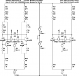
Here's the LTSpice schematic file. It has not been optimized much - just biased the Kulish predriver stage into linearity, biased the conventional CFP driver into linearity with comfortable current to drive the output stage, and bias the output stage to a comfortable quiescent current (in this case around 0.4-0.6 A). Input impedance at the base of the predriver stage simulates to over 1M, so it should easily work with a conventional Lin-Bailey-Self VAS biased to a few mA. Base stoppers are optional, but I just left them in as placeholders - they don't affect the distortion numbers much.
Attachments
Klaus, the capacitor between the emitter and collector in your circuit is counter-intuitive - in fact, anti-thematic. In normal operation, the signals at the collector and emitter are inverted in phase, but the cap attempts to nullify that and make them swing together. I'm not sure that I grok this correctly - I'll simulate it later to try to understand it.
Hi,
For the fun of it I tried true cascoding (constant Vce for both Q's) which worked out (more workable voltage range, better THD), and again that crazy cap did good for THD20 (which settled at 12ppm, and 2ppm below 2kHz THD). Another funny thing: When I increase drive impedance to a few hunderd ohms or so LF THD rises but THD20 actually goes lower.
A thing I still don't get by intuition is the load characteristic. More load == less gain (that's clear), but way less distortion also (not clear)...
A really interessting matter, this Kulish approach... I look forward to sim/try a little more sophistcated circuits with it, a full grown voltage amplifier stage, to be used without overall feedback...
Your output stage looks fine and quite unusual, too... personally I tend to prefer (at the moment) true class A in bridge mode, with high local feedback autobias scheme, for its superb power supply characteristics.
Regards, Klaus
It was only a quick try, nothing elaborated, just two legs of the posted circuit biased with an ideal CSS to the same operation point as the SE circuit. The THD wasn't any good at all... need to try harder it seems (or made a stupid mistake, maybe).Originally posted by linuxguru
> try on a LTP failed...
In what manner did it fail? Hard to bias, or Spice fails to coverge quickly, or is it worse than a conventional LTP under similar bias conditions?
I found that by lucky chance so to say (not from thorough analysing). Looking at in .AC analysis is interesting, too.Klaus, the capacitor between the emitter and collector in your circuit is counter-intuitive - in fact, anti-thematic. In normal operation, the signals at the collector and emitter are inverted in phase, but the cap attempts to nullify that and make them swing together. I'm not sure that I grok this correctly - I'll simulate it later to try to understand it.
For the fun of it I tried true cascoding (constant Vce for both Q's) which worked out (more workable voltage range, better THD), and again that crazy cap did good for THD20 (which settled at 12ppm, and 2ppm below 2kHz THD). Another funny thing: When I increase drive impedance to a few hunderd ohms or so LF THD rises but THD20 actually goes lower.
A thing I still don't get by intuition is the load characteristic. More load == less gain (that's clear), but way less distortion also (not clear)...
A really interessting matter, this Kulish approach... I look forward to sim/try a little more sophistcated circuits with it, a full grown voltage amplifier stage, to be used without overall feedback...
Your output stage looks fine and quite unusual, too... personally I tend to prefer (at the moment) true class A in bridge mode, with high local feedback autobias scheme, for its superb power supply characteristics.
Regards, Klaus
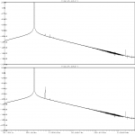
FWIW, I did a quick LTSpice sim of two LTP's - one using 2 kulish cells and the other a conventional LTP (as attached). I tried to keep the design parameters the same (or as near as i could  ) for both circuits and tuned the kulish implimentation for minimum distortion. The results looked quite good :
conventional LTP
0.019244%
Kulish LTP
0.000296%
about 65 times better ...
PS the design parameters are from an element of a circuit i am currently developing.
/dave
) for both circuits and tuned the kulish implimentation for minimum distortion. The results looked quite good :conventional LTP
0.019244%
Kulish LTP
0.000296%
about 65 times better ...
PS the design parameters are from an element of a circuit i am currently developing.
/dave
Attachments
DRC said:FWIW, I did a quick LTSpice sim of two LTP's - one using 2 kulish cells and the other a conventional LTP (as attached). I tried to keep the design parameters the same (or as near as i could
conventional LTP
0.019244%
Kulish LTP
0.000296%
about 65 times better ...
PS the design parameters are from an element of a circuit i am currently developing.
/dave
I think that if you just use a straight CFP dif pair, depending on the
component values, the reduction in distortion compared to the plain
vanilla dif pair will be similar.
cheers
Terry
Agree with Terry.
Also try to use Peufeu like config and the results will be better.
I just did a manual analysis of the Kulish stage and conclude it's like a Darlington config, using same tricks and little more to isolate first transistor but "energetically" or "economically" speaking is not a deal. Take any classical dual transistor stage and see you could obtain at least similar or better performances.
I think Kulish config could be a solution in small signal situation but not in VAS or driver stages. Such a current waste and so many transistors there could have a better use and greater global effect. Just my opinion...
The Kulish is far more linear than just about any other combination of two transistors, including the Sziklai - it's easy enough to simulate and verify this. It's also possible to tweak the harmonic response of the Kulish by playing around with the resistor ratios and the load.
Meanwhile, here is a more complete Class-AB amplifier design, loosely derived from Symasym, but with a Kulish predriver stage. It's only an outline for LTSpice simulation - there's room for a lot of circuit elaboration/improvement later.
Meanwhile, here is a more complete Class-AB amplifier design, loosely derived from Symasym, but with a Kulish predriver stage. It's only an outline for LTSpice simulation - there's room for a lot of circuit elaboration/improvement later.
Attachments
DRC, your LTP numbers look good - the only issue is that we lose gain in the LTP with the Kulish, so we have to regain it elsewhere, maybe in the VAS, to make the OLG respectable again.
As I've shown above, a non-Kulish LTP already gives respectable distortion numbers for the amp as a whole. By making the LTP a Kulish stage, we will gain small-signal linearity, but lose out on loop-gain to linearize the output stage - so there's a trade-off there. Some further circuit elaboration/optimization will probably throw more light on this.
As I've shown above, a non-Kulish LTP already gives respectable distortion numbers for the amp as a whole. By making the LTP a Kulish stage, we will gain small-signal linearity, but lose out on loop-gain to linearize the output stage - so there's a trade-off there. Some further circuit elaboration/optimization will probably throw more light on this.
hi linuxguru,
the LTPs i modelled both have the same gain (within 1%) and are swinging 30V p-p (ie 50% of the rail voltage). For the application i am invesigating this is the VAS stage of 'bridge' amplifier, it is modelled driving the OP into clipping (due to its lower voltage rails at +/- 15V). I agree this configuration would probably have little effect on an input diff stage.
Terry & DorinD , i will give the CFP / Peufeu (?) a try as well
BTW, i hope i am not thread-jacking but my output is a class A EF
Linuxguru,
I agree to you in a sense that some circuit elaboration could find an use to Kulish configuration. But firstly, look if you can obtain such kind of performances (or better) with not so cool circuits like that in fig.27 (to have some voltage gain):
http://www.dself.dsl.pipex.com/ampins/discrete/twoq.htm
or fig.29 for a simple buffer:
http://www.dself.dsl.pipex.com/ampins/discrete/cfp.htm
Those circuits are similar to Kulish but in my opinion are better. More than Kulish, permit to trade for specific performance and are not wasting too much current/voltage/devices for that. Just give them a try.
My sim is putting kulish in the lead !!
Hi,
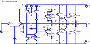
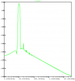
I did another sim with a CFP diff stage for comparison (attached). Hopefully, this is the correct configuration for CFP - i set the current for the inner NPN to a similar value to the kulish configuration.
again 30V p-p output :
std diff THD
0.019198%
kulish THD
0.000306%
CFP diff
0.002518%
It is worth noting that the kulish version's THD is very sensitive to resistor value ...
/dave
Hi,
I did another sim with a CFP diff stage for comparison (attached). Hopefully, this is the correct configuration for CFP
- i set the current for the inner NPN to a similar value to the kulish configuration.again 30V p-p output :
std diff THD
0.019198%
kulish THD
0.000306%
CFP diff
0.002518%
It is worth noting that the kulish version's THD is very sensitive to resistor value ...
/dave
Attachments
DorinD said:Those circuits are similar to Kulish but in my opinion are better. More than Kulish, permit to trade for specific performance and are not wasting too much current/voltage/devices for that. Just give them a try.
I would disagree. The circuits you've quoted are all feedback based where "Kulish Cell" is a true feedforward compensation approach, where adding two distorted currents results in an almost undistorted output. As a result it is much faster and it is also a very linear voltage to current convertor, useful in many applications.
In short - it is a different approach and could be a good alternative to more common NFB-based circuits.
Cheers
Alex
I am not quite sure whether this "Kulish Corrector" is a genuine piece of work. The design can be seen in a 1955 not commercial
tube amp ( for recording studios ) with selected triodes. Actually the idea may go back to a British patent from 1926 or so.
Next as an however retired mathematician I am amazed how could one take the simulation yielding TDH at face value that moreover has significance? Such simulation may work well for
"infinitesimally small" signal but certainly not for large signals.
Besides, how would one "in reality" measure TDH 0.000306%
where the error margin is not some magnitudes of 10 larger than the result?
I think the "Kulish Correction" simulation of nonlinearity will provide excellent results with tubes but in a semiconductor version the last authority is listening test.
Simply, when me and one of my cats sit and listen to Jarrett's Köln Concerto or Oregon's Winter Light and the cat says give me more of that then the amp and the speaker is ok. and I would buy a THD for 1 cent on the Dollar.
Dieter F.
> Actually the idea may go back to a British patent from 1926 or so.
Talk is cheap - produce the alleged patent. I fail to see how such
a triode-based circuit, even if one exists, could apply
directly to a transistor corrector which specifically uses
BJT parameters like Vbe and Vt in its construction.
> Such simulation may work well for
"infinitesimally small" signal but certainly not for large signals.
If you had an iota of a clue about Spice transient analysis, you would
have realized that the simulation data presented so far is entirely
*large signal* analysis, not AC small signal analysis.
The Spice simulation is mainly to gain insight about the operation
of the circuit - in particular, the direction in which a specific property
of the circuit responds to a specific change in a particular component/
parameter. It is not meant to be accepted as an absolute gospel truth
of how the circuit will behave in the real world, but rather as a first-
order approximation.
In reality, the transient analysis is accurate enough that it captures
parasitics, instability, etc. Just remove C2 in the last circuit that I
posted and watch the circuit oscillate at 4 MHz.
>how would one "in reality" measure TDH 0.000306%
Hook up a signal source at frequency f to the input, and use a high-Q
band-pass filters with centre frequencies of 2f, 3f, 4f, etc at the output.
Hook up an AC micro-voltmeter and measure the amplitude of each
harmonic - I see no conceptual difficulty.
Just FYI, there are simple circuits that can measure femto-amperes of
current.
>will provide excellent results with tubes but in a semiconductor version the last authority is listening test.
Regardless of whether it's a tube circuit or a transistor circuit, the objective
camp is going to insist on calculation, simulation, measurement, etc., while
the subjective camp is going to insist on listening tests. It has nothing to
do with the properties of tubes or transistors, or cat's ears or whiskers.
You mean Spice simulation simulates the quantum mechanical
"reality" of a semiconductor? Well yes if its executed on a CRAY...
you may see some results for large signal in a few seconds.
Of course it must necessarily be probabilistic if it indeed models
the physical reality.
If it comes to music I think it is not just objective reproduction of sound fields. Rather music "happens" as much inside ( the listener) as outside. Since it were far off topic I cannot even give a sketch of a proof of the following claim:
there is no sound field recorded on a CD but an objective description . An analog LP has more information no matter how many bits the word of the digital description has. Provided finite many.
In my opinion this applies to the objective vs. subjective camp.
Only iff the objective folks do not listen to music they stay objective. They judge the description.
The key question which cannot be a subject of this forum is can
the auditive sense be completely and consistently described as a theory? It pertains to nonlinear systems theory and thus if there is such a theory of the auditive sense it were from the outside transcomputational or in simple words it goes up in the smoke
of the emotional. And this emotional is what matters to the individual.
- Status
- This old topic is closed. If you want to reopen this topic, contact a moderator using the "Report Post" button.
- Home
- Amplifiers
- Solid State
- Kulish Corrector for Class-A EF O/P Stage