I would like to repeat my request posted here several times: To replace an old diode with a modern one.
But I lack the knowledge to adapt the APC - circuit of an old type like the very common Sharp-LT022MC to a modern diode.
As I wrote before, the company QSI produces laser diodes that could be a good base for repair.
Original designs differed in how anode and cathode of the laser diode and monitor diode are connected together.
QSI offers all variants. Adapter PCBs have to be designed, trivial.
http://qsilaser.com/download/Infra_Red/QL78F8SX_2019.pdf
I also have a batch of Rohm diodes, I think they are RLD-2WNM2
I also have adapter rings from the 9mm housing of the "classical" diodes to the 5.6mm of modern diodes.
So if ManoloMos or ASAMS have a candidate to replace an old type with a modern type, I could donate the parts.
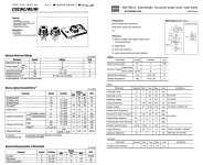
Datasheets of the Sharp and Rohm attached to calculate the APC.
But I lack the knowledge to adapt the APC - circuit of an old type like the very common Sharp-LT022MC to a modern diode.
As I wrote before, the company QSI produces laser diodes that could be a good base for repair.
Original designs differed in how anode and cathode of the laser diode and monitor diode are connected together.
QSI offers all variants. Adapter PCBs have to be designed, trivial.
http://qsilaser.com/download/Infra_Red/QL78F8SX_2019.pdf
I also have a batch of Rohm diodes, I think they are RLD-2WNM2
I also have adapter rings from the 9mm housing of the "classical" diodes to the 5.6mm of modern diodes.
So if ManoloMos or ASAMS have a candidate to replace an old type with a modern type, I could donate the parts.
Datasheets of the Sharp and Rohm attached to calculate the APC.
Attachments
in post #9 underOn ebay I have found this special Dutch guy for repair service on SONY laser units from KSS-Series:
https://www.ebay.com/itm/294757258722
https://www.ebay.de/itm/294757258722
At first glance it looks very interesting to me.
Any experiences ?
https://www.diyaudio.com/community/...laser-diode-its-the-lens.385706/#post-7374156
one will find further information
So...? What's the use of your post?in post #9 underOn ebay I have found this special Dutch guy for repair service on SONY laser units from KSS-Series:
https://www.ebay.com/itm/294757258722
https://www.ebay.de/itm/294757258722
At first glance it looks very interesting to me.
Any experiences ?
https://www.diyaudio.com/community/...laser-diode-its-the-lens.385706/#post-7374156
one will find further information
Hello! I have not tried it, but I think it should work? Most likely you will have to apply the APC circuit from a modern diode. By the way, the Chinese from Polida has taken root very well with me. Changed on two drives CDM1.Повторю свою просьбу, размещенную здесь несколько раз: Заменить старый диод на современный.
Но мне не хватает знаний, чтобы адаптировать APC - схему старого типа, как очень распространенный Sharp-LT022MC, к современному диоду.
Как я уже писал ранее, компания QSI производит лазерные диоды, которые могут стать хорошей базой для ремонта.
Первоначальные конструкции отличались способом соединения анода и катода лазерного диода и диода монитора.
QSI предлагает все варианты. Платы адаптера должны быть спроектированы тривиально.
http://qsilaser.com/download/Infra_Red/QL78F8SX_2019.pdf
У меня тоже есть партия диодов Rohm, кажется RLD-2WNM2
Еще у меня есть переходные кольца с 9мм корпуса "классических" диодов на 5,6мм современных диодов.
Так что, если у ManoloMos или ASAMS есть кандидат на замену старого типа на современный, я мог бы пожертвовать детали.
Даташиты Sharp и Rohm прилагаются для расчета APC.
check out the link in post #63So...? What's the use of your post?
Hello, please write your phone number in private messages, I am also from Ukraine, I have a few questions regarding KSS-272AHello!
I would like to share a joyful event.
Recently I have successfully restored Philips CDM1.
It turned out to be much more complicated than I imagined.
In order to dismantle the old laser diode LT022MC, it was necessary to cut off the top of the holder in which it is installed.
To do this, it was necessary to loosen the side mounting hexagon screw and completely remove the entire structure with prisms and mirrors. In the future, this entailed great difficulties with the installation and configuration of this unit and, accordingly, the diode separately.
The diode cannot be pulled out without sawing the clip, because it is firmly glued into it. It is impossible to heat in order to pull out the diode, you can lose the mirrors and spoil everything completely.
LT022MC bought on ebay from POLIDA seller. It works so far, the flight is normal!
Moreover, the position of the trimmer resistors remained the same.
Naturally, I twisted them, but in the end they returned to their original position.
Philips CDM 1 ?????? ????????? ?????. - YouTube
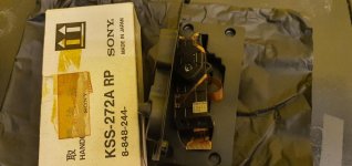
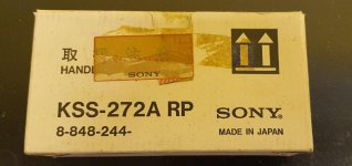
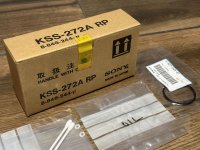
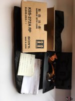
According the attached images of NOS parts it seems to be at least two versions:
1) KSS-272A RP "8-848-244" (older version in white package)
2) KSS-272A RP "8-848-244-II" (successor version in darker package)
In the late 1990s, when the KSS-272A was still readily available (I ordered mostly from Gehado - at those days German's distributor for SONY parts) and there available for low cost (90,- DM).
I only received versions in the dark packaging (MK-II).
What could have been the differences to those in the white package (without MK-II) ?
Maybe in the used laser diodes ?
Attachments
-
 Sony KSS-272A RP 8-848-244 made in japan-I.jpg54.8 KB · Views: 30
 -
 Sony KSS-272A RP 8-848-244 made in japan-II.jpg52.1 KB · Views: 28
 -
 Sony KSS-272A RP 8-848-244 MK-II made in japan-I.jpeg114.2 KB · Views: 24
 -
 Sony KSS-272A RP 8-848-244 MK-II made in japan-II.jpg95.6 KB · Views: 32
 -
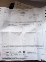 Sony KSS-272A RP 8-848-244 MK-II made in japan INVOICE.jpg104.5 KB · Views: 27
Hello everyone,
I found some SLD104 diodes on ebay and bought 2 pieces. I have already replaced one in an optical drive. Since I don't have the necessary equipment and I don't have much experience in electronics, so I cannot adjust the laser beam, I tested the new diode as it is. Unfortunately, although the laser beam is visible, the player does not read the disc, nor does it even spin it. Do you have any idea where I could start the diagnosis? In any case, this is an experiment, because I bought a disassembled Sony 559ES, for parts, with a defective laser.
I found some SLD104 diodes on ebay and bought 2 pieces. I have already replaced one in an optical drive. Since I don't have the necessary equipment and I don't have much experience in electronics, so I cannot adjust the laser beam, I tested the new diode as it is. Unfortunately, although the laser beam is visible, the player does not read the disc, nor does it even spin it. Do you have any idea where I could start the diagnosis? In any case, this is an experiment, because I bought a disassembled Sony 559ES, for parts, with a defective laser.
Это очень сложно сделать в условиях быстрого доступа, тем более нет уверенности в том, что эти диоды оригинальны и соответствуют параметрам, как указано в таблице данных. Для начала необходимо выяснить значение рабочего тока диода, одновременно контролируя его мощность генерации уже в собранном блоке. Физический диод должен быть установлен максимально точно в посадочное место старого диода. Далее самое сложное, регулировка фотодетектора, его в любом случае нужно будет срывать с места и заново регулировать. Остальное это навыки и понимание того, что вы делаете.
Успехов!🤝
Успехов!🤝
@dimon68 thanks for reply.
How can I find out the operating current of the diode? Where should I measure? The photodetector adjustment part is difficult, I don't have the necessary equipment for adjustment. As far as I know, since the disk is not detected/rotated, the diode power cannot be measured/adjusted.
How can I find out the operating current of the diode? Where should I measure? The photodetector adjustment part is difficult, I don't have the necessary equipment for adjustment. As far as I know, since the disk is not detected/rotated, the diode power cannot be measured/adjusted.
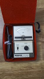
Для измерения мощности диода нужен специальный прибор, Laser Power Meter.
Ток диода смотрите в datasheet, он должен быть в пределах 50mA. не более.
Нужно одновременно контролировать ток и мощность излучения.
Без навыков и подручных средств эту идею реализовать практически невозможно.
Но всё равно желаю вам успехов.
Ток диода смотрите в datasheet, он должен быть в пределах 50mA. не более.
Нужно одновременно контролировать ток и мощность излучения.
Без навыков и подручных средств эту идею реализовать практически невозможно.
Но всё равно желаю вам успехов.
Attachments
@ASAMS Thanks for reply. It's just an exercise, I have nothing to lose, because I paid a little for these spare parts.
My questions are how can I measure diode current and where, and if it's mandatory not to spin the disc if the laser isn't adjusted.
Thanks in advance.
My questions are how can I measure diode current and where, and if it's mandatory not to spin the disc if the laser isn't adjusted.
Thanks in advance.
Ток измеряется на резисторе, обычно он 22Ω в схеме APC, по закону Ома.@ASAMS Спасибо за ответ. Это всего лишь упражнение, мне терять нечего, так как за эти запчасти я заплатил немного.
У меня вопросы, как и где измерить ток диода, и обязательно ли не крутить диск, если лазер не отрегулирован.
Заранее спасибо.
Last edited:
Thanks. According to schematics, there are 2 resistors, one of 2k2, and one of 10 ohms, next to the base, respectively the emitter of the transistor in the APC circuit (if the schematics presented here is correct).
I mus appologise to all of you, I'm not trying to discover the wheel, just doing some practice.")
Thanks in advance.
I mus appologise to all of you, I'm not trying to discover the wheel, just doing some practice.
Thanks in advance.
- Home
- Source & Line
- Digital Source
- KSS-272A Substitution of laser diode