Its voltage is set to -34V (minus thirty-four volts) so there is no problem there. However, the file from post 341 doesn't have a "C" node, just as Scott said. I get the error message too when trying to simulate it. Could the label have been deleted by mistake when adding the resistor perhaps?
For the file from post 341, with the output renamed to "C" and the frequency changed to 20kHz I get:
Which is the same as Scott got.Code:Circuit: * C:\joakim\spice\krill\Krill20\Krill20.asc Direct Newton iteration for .op point succeeded. Fourier components of V(c) DC component:0.00348593 Harmonic Frequency Fourier Normalized Phase Normalized Number [Hz] Component Component [degree] Phase [deg] 1 2.000e+04 2.875e+01 1.000e+00 -0.02° 0.00° 2 4.000e+04 4.201e-03 1.461e-04 -84.23° -84.21° 3 6.000e+04 9.634e-03 3.350e-04 4.27° 4.29° 4 8.000e+04 2.170e-04 7.546e-06 -103.50° -103.48° 5 1.000e+05 8.697e-04 3.025e-05 -11.36° -11.33° 6 1.200e+05 4.476e-05 1.557e-06 75.58° 75.61° 7 1.400e+05 1.091e-04 3.794e-06 33.54° 33.56° 8 1.600e+05 4.157e-05 1.446e-06 100.64° 100.66° 9 1.800e+05 5.227e-05 1.818e-06 -167.91° -167.89° Total Harmonic Distortion: 0.036687%
For the unchanged file from post 302 I get:
1kHz and 20kHz figures are similar.Code:Fourier components of V(c) DC component:-0.00994689 Harmonic Frequency Fourier Normalized Phase Normalized Number [Hz] Component Component [degree] Phase [deg] 1 2.000e+01 2.829e+01 1.000e+00 -0.00° 0.00° 2 4.000e+01 8.461e-03 2.991e-04 -90.16° -90.16° 3 6.000e+01 6.187e-03 2.187e-04 -0.18° -0.18° 4 8.000e+01 6.272e-05 2.217e-06 87.42° 87.42° 5 1.000e+02 2.729e-04 9.646e-06 0.03° 0.03° 6 1.200e+02 3.728e-05 1.318e-06 -89.88° -89.88° 7 1.400e+02 1.008e-04 3.564e-06 0.03° 0.03° 8 1.600e+02 7.917e-06 2.799e-07 89.43° 89.43° 9 1.800e+02 6.475e-06 2.289e-07 0.87° 0.87° Total Harmonic Distortion: 0.037071%
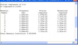
However, for the same devices rearranged into a triple EF (KSC3503/KSA1381, 2SC4793/2SA1837 and 4 pairs of Q2SC5200/Q2SA1943), and only 100mA (half of what is used in the post 302 amplifier) of bias per pair, I get less than a third of these distortion numbers:
20Hz and 20kHz figures are similar.Code:Fourier components of V(c) DC component:-0.000219481 Harmonic Frequency Fourier Normalized Phase Normalized Number [Hz] Component Component [degree] Phase [deg] 1 1.000e+03 2.876e+01 1.000e+00 -0.00° 0.00° 2 2.000e+03 2.723e-03 9.467e-05 -88.97° -88.96° 3 3.000e+03 3.303e-04 1.148e-05 8.74° 8.74° 4 4.000e+03 4.723e-04 1.642e-05 -88.91° -88.90° 5 5.000e+03 1.531e-04 5.321e-06 -3.55° -3.55° 6 6.000e+03 1.681e-04 5.844e-06 -88.33° -88.33° 7 7.000e+03 3.353e-04 1.166e-05 0.41° 0.41° 8 8.000e+03 6.110e-05 2.124e-06 -88.68° -88.67° 9 9.000e+03 2.128e-04 7.399e-06 -0.18° -0.18° Total Harmonic Distortion: 0.009809%
The 8 ohm load is quite light for 4 pairs of output transistors in an amplifier powered by +-34V... But transistors are cheap nowadays, so using lots of output transistors isn't such a bad idea for lowering distortion.
I don't think anyone has claimed that the Krill would sound bad. What was said was that Scott's simulation results were off. I posted my results to show that Scott's numbers from post #354 could be reproduced.
BTW, by increasing the triple EF bias to the same amount as in the Krill, the 7th harmonic goes down and the THD goes up. Like that, the numbers look just like the Krill.
For the basic circuit as shown but optimised with different device models, I
get 0.0055% THD (1kHz) and a very good harmonic spectrum. This
corresponds to a standing bias of about 160mA / OP device. There is a
definite distortion null happening just as Steve reported.
Unfortunately it is quite clear that Ltspice is not so good in simulating the
whole section that works in/near saturation so I also did a simple DEF OP
stage, as per Krill topology to see where and if the null would still work. It
does indeed still exist and with 180mA OP bias it sims around 0.0035% at
1kHz. Same 8R load and 30V swing. The harmonic spectrum is very good
with H7 at near -130dB.
The null is very dependent on which device models are used, so clearly
Ltspice is not reliable for this type of circuit.
The caveat is indeed at higher frequencies, where the stored charge
effects manifest, however this can be optimised to a dgree with the right
cap size across driver emitters. Too big and it goes more out of class A,
too small and the charge effects start manifesting in cross conduction.
I will post more details later with plots but am busy right now.
Terry
Thanks Hugh,
Just tried another set of device models for pre drivers in Krill circuit.
This time tried 2240/970, had to re locate the distortion null.
Distortion is now down to 0.0034% / 29V / 8R 1kHz.
Clearly we are looking at Ltspice not representing accurately what is
happening in the circuit.
Terry
Just tried another set of device models for pre drivers in Krill circuit.
This time tried 2240/970, had to re locate the distortion null.
Distortion is now down to 0.0034% / 29V / 8R 1kHz.
Clearly we are looking at Ltspice not representing accurately what is
happening in the circuit.
Terry
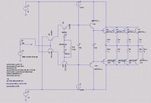
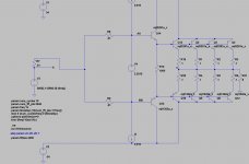
Here is the asc file that I have been playing around with.
OP sevices and drivers are mjl1302a_x courtesy Andy_c
.MODEL mjl3281a_x npn IS=9.8145e-12 BF=438.0 NF=1.00 VAF=38 IKF=19.0
ISE=1.0e-12 NE=1.1237388682 BR=4.98985 NR=1.09511 VAR=4.32026
IKR=4.37516 ISC=3.25e-13 NC=3.96875 RB=3.997 RE=0.00 RC=0.06
XTB=0.115253 XTI=1.03146 EG=1.11986 CJE=1.144e-08 VJE=0.468574
MJE=0.34957 TF=2.6769e-9 XTF=7500 VTF=3.0 ITF=1000 CJC=1.093685e-9
VJC=0.623643 MJC=0.482111 XCJC=0.959922 FC=0.1 CJS=0 VJS=0.75
MJS=0.5 TR=1e-07 PTF=0 KF=0 AF=1 Vceo=200 Icrating=15
mfg=OnSemiconductor
.MODEL mjl1302a_x pnp IS=9.8145e-12 BF=122.925 NF=1.00 VAF=40 IKF=19
ISE=9.18577762370362E-07 NE=5.0 BR=4.98985 NR=1.09511 VAR=4.32026
IKR=4.37516 ISC=3.25e-13 NC=3.96875 RB=3.30 RE=0.00 RC=0.06
XTB=0.115253 XTI=1.03146 EG=1.11986 CJE=1.561e-08 VJE=0.781803
MJE=0.433868 TF=3.257e-9 XTF=1000 VTF=2.0 ITF=260 CJC=2.346838e-9
VJC=0.27876 MJC=0.411324 XCJC=0.959922 FC=0.1 CJS=0 VJS=0.75
MJS=0.5 TR=1e-07 PTF=0 KF=0 AF=1 Vceo=200 Icrating=15
mfg=OnSemiconductor
Pre drivers 2SA970, 2SC2240
.model 2sa970 PNP(Is=465.4f Xti=3 Eg=1.11 Vaf=57 Bf=407.6 Ise=4.683p
Ne=2.051 Ikf=.3998 Nk=1.192 Xtb=1.5 Var=100 Br=1 Isc=465.4f Nc=1.048
Ikr=6.032 Rc=2.343 Cjc=11.59p Mjc=.4014 Vjc=1.155 Fc=.5 Cje=5p
Mje=.3333 Vje=.75 Tr=10n Tf=1.252n Itf=1 Xtf=0 Vtf=10)
.model 2SC2240 NPN(Is=1.41f Xti=3 Eg=1.11 Vaf=100 Bf=310 Ne=1.5 Ise=0
Ikf=70m Xtb=1.5 Br=.8893 Nc=2 Isc=0 Ikr=0 Rc=30 Cjc=6.878p Mjc=.2725
Vjc=.75 Fc=.5 Cje=5p Mje=.3333 Vje=.75 Tr=10n Tf=1.276n Itf=0 Vtf=0
Xtf=0)
Change the .txt to.asc. Note changes I made were to use ideal CCS top
and bottom. The existing CCS's were a) low in OP Z and b) not matched,
this had an effect on result. I got best result with same drivers as OP
devices.
WRT pre drivers 2240/970 gave lowest THD but other devices gave higher
THD and nicer spectrum ie; lower H7/8/9.
If you play with the value of R14, the null becomes very apparent and it is
quite sensitive.
THD at 1k is very low (for an OL design). At 10k it rises to about 0.008%.
If you play with the value of C1 you can see it's effect on THD and X
conduction. 0.1uF seems to be about the best compromise.
Changing the load to 4 ohms throws the whole thing off and the distortion
null needs to be re adjusted. Whether this is a product of Ltspices inability
to replicate accurately real BJT characteristics or if it is in fact a real circuit characteristic I don't know.
cheers
Mr T
Attachments
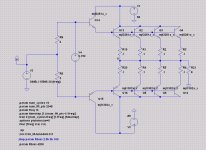
Here is the basic OP stage that I worked on to identify the distortion null.
The rails are a bit higher at 55V.
In this case the null is very pronounced and THD at 28V / 8R / 1kHz is
<0.002% Again if you vary the value of V4 you will see the THD climb out
of the notch.
The circuit clearly has distortion cancelling properties. How dependent on OP
load the null is, in reality, remains to be seen.
T
Attachments
I knew that Hugo but I just thought that it should be pointed out that the usual suspects who decided to wreck this thread had their own invitation-only forum!If you want an explanation for the pulled post:
Lets be constructive.
But you already knew that.
/Hugo
Anyway, Terry is putting this thread back on track
")
Thank You for being so vigilant
This post got pulled by accident:
Nice posts, Terry, this is the sort of info I was hoping the thread would start to tease out, way back when Steve kindly posted his first revelations of the circuit - well done, maybe now we can proceed to build & analyse it.
Hi Terry D - Thanks for all of your work and posting the results. Hmmmm....... different output devices - I'll bet that Dr. Phil - PH104 - is adding those on to his to do list. I know that when I get a chance to get back to building that I will be strongly tempted to play around a bit - but that gets me back to "messing around" rather than the preferred "sit back and listen" mode. Now that the wife's health problems have been addressed and she is in good health I should be able to find some time and be able to contribute to the thread.
Great stuff Terry. Thanks! I'm about to finish up a 50W Krill with some transistor and current changes from Steve's original schematic. I considered the C2240/A970 pair for the Q9/Q10 positions in your post 403 but went with the 2SA1360/2SC3423 pair instead. I also used the 2SA1360/2SC3423 in the Q7/Q8 positions because of power dissipation (nearly 1W).
The capacitor info is also very useful and interesting. Have you looked at the effect of the value of C7? The largest I've used is 1uF but haven't done any comparisons with different values.
Thanks again. It's nice to see some sim results that builders can use for optimization.
Phil
The capacitor info is also very useful and interesting. Have you looked at the effect of the value of C7? The largest I've used is 1uF but haven't done any comparisons with different values.
Thanks again. It's nice to see some sim results that builders can use for optimization.
Phil
Hi Terry,
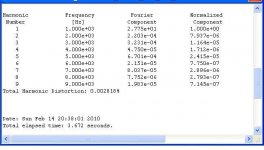
Thank you for that input. I think everything you discovered about my circuit is correct. At lease it duplicates what I observed. Here is what I had posted as the "claimed" THD back in post 131:
That looks close enough to the results you posted to satisfy me.
I agree with you about LTspice. I do not plan to use it in the future unless necessary.
You are correct in regards to the null. It will change with different devices, but it is always there. Fortunately, most people will not attempt to set the bias until the amp is built. At that time, you simply set the bias while looking for the null, if you have a distortion meter.
You are also correct that the null changes with some with the load. Set the bias using the load you will be driving. In my case that is 4 Ohms. Most DIYers will know the average impedance of their speakers.
It is really nice to have some positive input, especially when it seems to agree so closely with what I had observed. Thank you.
Thank you for that input. I think everything you discovered about my circuit is correct. At lease it duplicates what I observed. Here is what I had posted as the "claimed" THD back in post 131:
Fourier analysis for v(47):
No. Harmonics: 10, THD: 0.00248421 %, Gridsize: 200, Interpolation Degree: 1
Harmonic Frequency Magnitude Phase Norm. Mag Norm. Phase
-------- --------- --------- ----- --------- -----------
0 0 -0.12172 0 0 0
1 1000 28.2861 -0.0092264 1 0
2 2000 0.000657583 71.3428 2.32476e-005 71.3521
3 3000 0.000128306 -151.08 4.53601e-006 -151.08
4 4000 8.10099e-005 100.802 2.86395e-006 100.811
5 5000 0.000170485 -0.65197 6.02717e-006 -0.64275
6 6000 4.31291e-005 83.065 1.52474e-006 83.0742
7 7000 6.33176e-005 43.2346 2.23847e-006 43.2439
8 8000 4.00605e-005 85.5068 1.41626e-006 85.516
9 9000 4.22854e-005 76.0533 1.49492e-006 76.0625
That looks close enough to the results you posted to satisfy me.
I agree with you about LTspice. I do not plan to use it in the future unless necessary.
You are correct in regards to the null. It will change with different devices, but it is always there. Fortunately, most people will not attempt to set the bias until the amp is built. At that time, you simply set the bias while looking for the null, if you have a distortion meter.
You are also correct that the null changes with some with the load. Set the bias using the load you will be driving. In my case that is 4 Ohms. Most DIYers will know the average impedance of their speakers.
It is really nice to have some positive input, especially when it seems to agree so closely with what I had observed. Thank you.
Hi Phil,
I think Terry mentioned C7 as having some effect. That has been my observation also. The change from 0.1uF to 10uF is fairly small. I did evaluate different values for C7, both by testing and listening. Oops! I used that word again. I settled on 1uF as a common value to make things less complicated.
The capacitor info is also very useful and interesting. Have you looked at the effect of the value of C7? The largest I've used is 1uF but haven't done any comparisons with different values.
I think Terry mentioned C7 as having some effect. That has been my observation also. The change from 0.1uF to 10uF is fairly small. I did evaluate different values for C7, both by testing and listening. Oops! I used that word again.
I settled on 1uF as a common value to make things less complicated.Thanks Steve. I think Terry's comments were about the new C1 between the driver emitters on his schematic but I might have missed any comment about C7 as I stopped paying attention here several pages ago. I'll keep the 1uF MKP cap for C7 as it fits nicely on your board then use a bigger one on the modified output I'm building on a proto board once I get back to that project. I think I've got some reasonable quality/size 10uF around 
I hope to get at least one 50W board done next week and now have a pair of speakers (Klipsch Forte) that are happy with smaller amps instead of the 83 dB efficiency Mirage's in the main system so maybe I can finally do some Krill listening (along with some ).
).
I hope to get at least one 50W board done next week and now have a pair of speakers (Klipsch Forte) that are happy with smaller amps instead of the 83 dB efficiency Mirage's in the main system so maybe I can finally do some Krill listening (along with some
).Thankyou Terry for taking the effort to put together a schematic and model file to work with. I don't know if it's just a little carelessness or just plain ennui after all this time that caused Steve to post #341. I took your circuit and placed a voltage source where C7 was and drove it as a plain Darlington output. The THD was ~.005% as is. I'm surprised and a little embarrased that no one pointed this out before. This is a null point vs the bias voltage as Bernie Oliver pointed out a long time ago.
The DC bias is about the same (50-60W) as I ran my Hafler 220 at with no problems.
The DC bias is about the same (50-60W) as I ran my Hafler 220 at with no problems.
Attachments
Last edited:
I suppose what would follow is a nifty circuit to keep the optimum bias voltage regardless of load and temperature...
What documentation is there of this phenomenon? Any links?
- keantoken
PTAT for temp for load your call. I might point out also that any real speaker load will not have 0 phase as a resistor does so any residual cancellation will be compromised.
To the discredit of the engineering community (myself included), no one sat down and spent serious time examining in detail what was going on here. I did not help to have an ever changing target. In the end there were knee jerk responses for what were technically unsound explanations.
So thanks again Terry for finally providing the files that exhibit some interesting behavior. I returned to them for a while and probed around a little. First I made C7 really big (10000uF) so there was no question that the bases of the output Darlington were tied (AC) together. This made a very slight but immaterial difference. So now one can do a Fourier analysis of the voltage just after the “strangely” connected devices and see that there is a phase difference in the third harmonic (re. the output). An ordinary weak compressive nonlinearity usually would have the same phase. So in essence the saturated devices act as a weakly nonlinear resistance now capable of subtracting from the output nonlinearity. The “tuning” is really just changing the output bias to find the well known null point (I don’t know where Bernie Oliver’s analysis is published). Sort of a feed forward error correction.
Removing the input devices and replacing them with a voltage source of exactly the same value showed that this was the same “sweet spot”. Changing this voltage only 10mV to each side confirmed this. The “raw” DEF distortion is about .005% which is partially canceled down to ~.003%. Unfortunately this only works for purely resistive loads of a single value. Making the load 8 Ohms at 90 degrees and the distortion comes back (in fact this seems to also destroy the distortion null). This in itself is worth exploring. I never explored the DEF distortion null with a real speaker load.
If you probe around Terry’s simulation you will see that there is no wild behavior, unusual charge storage effects, etc. going on. A DC sweep will also show that the characteristic “S” shaped nonlinearity is morphed into a more curvy shape due to the partial cancellation of the thirds.
One other thing, there is a turn on transient and I’m not familiar enough with LTSPICE to be sure there is no contamination of the results by this.
LT spice seems rather optimistic..
with a 200ma bias per devices, 1KHZ, 50V PP
my simulator indicate about 0.08% for steve s OS
and 0.05% for a triple emitter follower...
I believe you haven't found the null, for all my sims it was below 200mA.
I believe you haven't found the null, for all my sims it was below 200mA.
well, i did take the value recomended by steve for his output stage..
that said, optimising the bias for both comparative stages,
the triple EF yield 0.02% and the krill is 0.05%,
at 50V PP , 1khz , 8 ohm..
that s an order of magnitude higher that what is claimed by there..
- Status
- This old topic is closed. If you want to reopen this topic, contact a moderator using the "Report Post" button.
- Home
- Amplifiers
- Solid State
- Krill - The Next Generation