jkeny said:I also believe OStripper's idea of using flat diodes on the bias board for better contact with the heatsink to be well worthwhile.
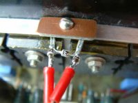
Jens Rasmussen (Delta Audio) did the same thing a few years ago with his Leach pcb. I initially did that too, and even sanded the faces as a unit to achieve better contact, but a simple experiment showed that a much faster thermal response could be achieved by using axial diode leads clamped to the heatsink (via Kapton insulation tape), as shown. I found three diodes to be optimal for the Leach.
Regards,
Brian.
So, Brian, let me get it straight - form the pics I see the 3 diodes in the air with two soldered leads conducting heat from the heatsink (& obviously insulated from the heatsink). And this has a faster thermal response? And is unaffected by air currents? Hmmm!
Edit: thinking about it metal would be a better heat conductor than the glass or plastic body of the diode, so I'm convinced!
Edit: thinking about it metal would be a better heat conductor than the glass or plastic body of the diode, so I'm convinced!
This is the "as shown"
I really do not see that working too well. Leach put his diodes
through holes in the HS (aluminum 100% in contact with the
body of the round diode) , A Vbe tranny has 2-3 sq. cm's
of area. But glass is a insulator, so that might be only
way.

(glad I'm using the "flatties")
OS
ostripper said:
I really do not see that working too well. OS
It actually worked very well on my Leach version, and it's a sight better than drillling the heatsink.
Anyway, try the “ouch” test!
Hold the diode body between thumb and finger. Apply a hot soldering iron bit to the lead. Time your “ouch, better drop it” response as the body (and fingers) heats up. Now do the same but hold the opposite lead instead of the body. Betcha drop it sooner!
The three diodes are mounted so that four leads make heatsink (h/s) contact. Four diodes mean six leads making contact; all contributing thermal transfer to the PN junctions. Any mass of insulation i.e plastic or glass body or air, will obviously slow down that transfer rate.
The important point is that the leads, or SMD legs, make contact with the h/s, not via an air gap. I suppose a double sided pcb with enough via holes might allow a faster transfer rate.
One could make a flatpack of axial leaded devices with leads through the pcb, bent flush with the pads and soldered, then filed flat. The whole unit can then be clamped via an insulator to the h/s. That way all leads are in contact with the h/s.
By the way, I used the SOD123 package with that technique, which I think is even smaller than the one you’ve used, i.e. less thermal mass. SOD323 would be even smaller. Sanding the faces can further reduce that mass, within reason, of course.
Brian.
Brian,
I think that is what OS is intending - having the metal diode leads in thermal contact with the HS & soldering longer leads back to the pcb. In other words the diode has it's leads facing away from the pcb towards the HS!
I see more metal area conductivity evident in your scheme though & possibly a quicker response therefore
ostripper said:That is a good idea, the metal leads "wrap around" the body
and are flush with one of the sides. (attached)
One could just flip the
plastic side toward the board (flat metal away from PCB)
and couple using a compounded
mica washer.
best of both worlds..
OS,
I'm not sure how this works at all. If the legs of the SMD are soldered to the pcb surface, how do they contact the heatsink?
Are the bodies glued to the pcb, dead beetle style, then the leads soldered in a string?
A sketch would help.
Thanks.
On a PC note, in my previous post, I'm not advocating that one deliberately burns their fingers; drop it before then.
Brian.
jkeny said:Brian,
I think that is what OS is intending - having the metal diode leads in thermal contact with the HS & soldering longer leads back to the pcb. In other words the diode has it's leads facing away from the pcb towards the HS!
I see more metal area conductivity evident in your scheme though & possibly a quicker response therefore
Thanks jk,
You posted while I was composing.
O.k. I see, but that construction technique will be a little more tricky than axials through the board.
Oh, and the leads can be long, increasing the contact area, if necessary.
Brian.
Diode bias sensor
While we are on this subject (it's not too far OT, is it?) I've often wondered whether a rectifier diode, 1N400X might not be as good as a signal diode, 1N4148,1N914 etc. The former has a thick lead, hence larger contact surface but a bigger PN junction area so might not respond as rapidly as a signal diode’s smaller PN junction, but this has thin leads. Does it matter, or am I nit-picking?
On the other hand, thermal tracks use rectifier types, so probably fine.
Brian.
I pondered this as well. On a standard "leach" ,the Vbe is
just a crude shunt regulator , locked to a preset voltage,so
any diode would do nicely.
The krill is different , it's bias is dynamic , with the diodes
altering the saturation of the 2 transistors with
the waveform at VERY low currents , so speed is a factor.
I suspect , IF you did use slower (1n4001..etc.) diodes,
the special advantages of the krill OPS would be
compromised , especially at HF.
OS
c2cthomas said:
Should be OK - I did the matching myself with Steve sitting next to me.
On the other hand - two wrongs don't make a right....

But three lefts does.
I am back from testing for a few days. I will have more next tests week.
jmmartins said:Hi Andrea
How much offset are you getting without R30 - R33?
Good work!
Hi,
I didn't measure offset yet. It can be nulled, in absence of R30..33, adjusting R26.
jkeny said:Andrea,
Did reversing the bias leads solve your problem?
Hi, the bias leads have always been connected in the right sense. Connecting them backwards would have caused a higher current, not a lower one.
For the moment I just heatsinked Q7 and Q10 (I used the same heatsink for both to get some thermal tracking as well).
Both channels behave in the same way, only with different degrees (the one with better heatsinking -mica and goop- passes less current, nearly 70mA, the one with sil-pads passes more current because it runs hotter)
Ciao
Andrea
Andypairo said:
Thomas,
I have no doubt they are good transistors.
This evening I completed the second board and, after tapping the heatsink (and breaking a tap
To be quicker I didn't use the usual mica-thermal grease insulators but some sil-pads.
Unfortunately the effect is almost the same.
Almost because the higher thermal resistance of the silpads makes the output BJTs (slightly) warmer so they pass some more current.
It looks like I'm using a too good heatsink
To get a confirmation I tried lifting one of the output BJTs from the heatsink and its current started increasing.
So the ouputs are running too cool relatively to Q7 and Q10 that arelike hell (cannot keep my finger on them).
It seems I can't do anything different than either heatsinking Q7 and Q10 or "downgrading" the amplifier to a 50W amp (or something in between 50 and 100W)....
Open to suggestions....
Ciao
Andrea
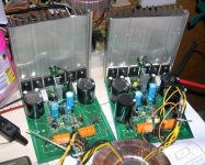
If heat sinking Q7 and Q10 solves the problem, then do it. Could you post some information on your heat sink. A picture would be nice.
How close to the outputs is the bias board mounted?
Hi Steve,
the heatsink on Q7-Q10 is a sub-optimal solution IMHO, mostly because on the "correctly" heatsinked board I still can't pass more than 70mA, even with R27 at maximum setting.
On the other board, with less good connection to heatsink (sil-pads), I can easily adjust bias to over 200mA.
These heatsinks are nothing special, they measure 15x17x4cm and their base is not particularly thick (about 5mm).
But since a photo is better than many words...
The board on the left misses some components because was assembled in a hurry
Ciao
Andrea
Attachments
- Home
- Amplifiers
- Solid State
- Krill construction thread - 100W version