
Although my language skills are excellent for a Brit, ( after 10 years as a roadie, I can order beer, coffee, 3 phase 200A supplies, and various illicit items in about 12 languages), I have to draw a line at French technical publications. ")
Any English language references?
Any English language references?
jacco vermeulen said:
Aaron,
why do Aussies are the only with those huge sinks,mate.
Is that tobacco i am seeing in the corner ?
No tabacco here! I don't smoke
Not sure why we are the only one with those sinks mate, i'm sure they'd come from o/s and not made here... In fact, i'd guess china (where half our heatsinking supplies are made aparantly for large orders... it's cheap!)Dissapating about 150w of heat they are sitting at under 20deg above ambient (fan cooled) so that's impressive!!
pinkmouse said:Hmm, those resistors look very familiar...
So how hot are your predrivers running, Aaron? Are those little bits of ally sheet adequate?
Familiar? Nah
I quite literally have hardwired everything... something i'm SURE i'll regret in future i'm sure, but for now, it's solid AS and nothing is coming off anytime soon (pending any failures!) This is my final 2... the third is not in the photos My pre-drivers were hitting about 58deg with the pieces of ally sheet on when there was no outputs connected.... However now they sit at 45deg (20 above (in deg C)) solid.... Not sure why they are cooler now, but my drivers hit 58deg (about 33 above ambient) and are noticably hotter now when i have more outputs... Considering i've got to more than double my bias, i am wondering a little about cooling, but i guess i'll fix that when time comes due!
Upupa Epops said:Aaron, how are fitted belts with transistors to heatsink ? By screws on narrow side ?
It's a piece of ally strip that i cut to the right size and bent with test and fit method! Works a treat! The transistors are screwed (through the tab, straight through the ally through the pre-made heatsink)... I used mica washers that i cut up from an old amp (they are EXTREMELY thin, talking, push them a little and they break into bits!) so it goes transistor - mica - "belt" - heatsink all with smeared grease between every joint to make sure it gets heat transfer!
Aaron
pinkmouse said:Any English language references?
You can find the book on audio amplifiers of Marshall Leach on his homepage.
Mr John Curl researched TIM together with Matti Otala.
Mr Curl's JC1 and JC2 are famous designs.
Otala worked for Harman Kardon for over a decade.
Mr Curl with Parasound, his JC1 evolved to the Halo JC1 power amplifier, imo it has all the characteristics of an amplifier aimed at low TIM : Speed, Speed, Speed.
Undoubtebly you can find lots of info at Parasound and Harman Kardon, in English of course.
I can not imagine you would not find plenty reference here with a search !
Illicit items ?

(makes me recollect i almost had a date with a british customs girl because of my posh brit accent, she had nice illicit items
 )
)Upupa Epops said:To Aaron : Thickness of belt is app. 8 mm ? I mean that for better heat transfer should be using of L - profile.
Thickness of the belt is 1mm!! It's very thin... About 25mm high...
L shape would be better, but i can't bend it like i needed to to make a good thermal connection for the bias transistor
It is very thin so conducts heat very well
Aaron
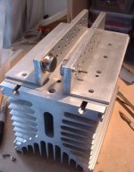
Here's a picture of my idea for the output stage and heatsink so far.
Each side will be connected to one rail, and the whole angle isolated from the heatsink. This will hopefully offset the problem that my angle extrusion may be a bit thin, as will the extra heat spreader bolted to the trannies
Each side will be connected to one rail, and the whole angle isolated from the heatsink. This will hopefully offset the problem that my angle extrusion may be a bit thin, as will the extra heat spreader bolted to the trannies
Attachments
pinkmouse said:I think you two are talking at cross purposes!
Aaron is talking about the thin ally plate on the drivers, and Pavel is talking about the mounting ribs on the heatsink extrusion...
Ah ha! The man has cracked the cookie! It makes sense now!!!
Sorry, cross language!
The ledge is 6mm thick........ the heatsink is 0.25c/w......
Do you mean L profile as in a screwed on one? Or you mean something different? Put up a picture so i know what you mean
The heatsinks seems good enough for me now
I'm not sure though how i'm going to work it into the case.... 3 heatsinks (and everything else! 3 of!) that are 300mm long by 152mm high....... plus depth, plus toroids (170x70), plus caps, plus turn on circuits, etc.......
thinking i might make a "long" amp - about 900mm long about 250mm high and about 250-300mm wide....... Bit stuck for design with this!
pinkmouse said:Here's a picture of my idea for the output stage and heatsink so far.
Each side will be connected to one rail, and the whole angle isolated from the heatsink. This will hopefully offset the problem that my angle extrusion may be a bit thin, as will the extra heat spreader bolted to the trannies
Why not have non-live heatsinks? Wouldn't you be better isolating each transistor rather than the L bracket from the heatsink? (which may comprimise performance??)
Just a thought....
I wished i could have live sinks though, would make it so much easier to build.... (and electrocute myself!)
Aaron
The heatsink itself will be isolated, but each angle will be connected to one rail. I have some large sheets of silpad, (you can just see them in the picture), between the angle and the 'sink. My idea was to use as much of the ally as possible to spread the heat. This will hopefully allow me to get by without having to go out and get some thicker angle.
NUTTTR said:I'm not sure though how i'm going to work it into the case.... 3 heatsinks (and everything else! 3 of!) that are 300mm long by 152mm high....... plus depth, plus toroids (170x70), plus caps, plus turn on circuits, etc
Calling it Mad Max is out of the question, that one is taken for my protegés.
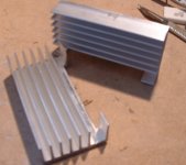
Gorgeous heatsink, Al.
"This transistor have fullinsulated case = easy mounting. "
About the same mounting as the MJE15032 actually and uses the same type of mica insulator. It is a TO-126 case and that too has an exposed metal back for heat transfer. Similar to the MJE340 which Krell ised to use in the early versions.
MArk
About the same mounting as the MJE15032 actually and uses the same type of mica insulator. It is a TO-126 case and that too has an exposed metal back for heat transfer. Similar to the MJE340 which Krell ised to use in the early versions.
MArk
jacco vermeulen said:Gorgeous heatsink, Al.
Not bad, is it!
I spent a couple of hours this morning lapping every surface flat with 1200 wet and dry, on a sheet of glass on the bed of my table saw. It's surprising how uneven an apparently flat surface can be.
Upupa Epops said:Insulating of L - bracket is precise solution, 'cos you get excelent rail conductor, much better than in " standard case ( by wire ) ". Also heat conductivity will be more better and temperature feedback too.
That's what I was hoping, it's nice to be confirmed by an expert!
Here's the smaller heatsinks for the driver board:
Attachments
depends...
...who you ask, but IMHO 65c is too hot. I try and keep things 'safe' too touch, so 55c total, ie 30c above ambient is about it. Another good point for cool is longevity, about 10 times the life for 55c versus 65c...
You'll thank me after you've touched the things a few times...
Stuart
...who you ask, but IMHO 65c is too hot. I try and keep things 'safe' too touch, so 55c total, ie 30c above ambient is about it. Another good point for cool is longevity, about 10 times the life for 55c versus 65c...
You'll thank me after you've touched the things a few times...
Stuart
tmblack said:How hot is too hot for predrivers for reliable operation?
My heatsink reaches 65C or 45 above ambient.
Tom
I have seen the pre-drivers/ VA devices on an Adcom 555 run without heatsinking in the 65-70c range. The amps have survived for over 15 years hoever for people that like to leave their amps on overnight or longer periods, I see the PCB's scorched and in one case the device failed.
It would be better As Stuart says to keep them at about 55c for long term reliability.
Hi pinkmouse,
re post 1268 & pic. The plate inside the angle will add very little (if anything) to the dissipation of the heatsink and angle combination. Save yourself some drilling on the next one you build.
It looks like you intend bolting the angle to the heatsink using Tee nuts in the slots. This will tend to bend the angle preventing contact between the heel of the angle and the heatsink. Can I suggest a row of bolts (no.10s) along the heel of the angle as close into the corner as you can manage to ensure good contact and heatflow. A similar row along the toe will add no improvement because it is too remote from the heatsource.
pinkmouse said:I spent a couple of hours this morning lapping every surface flat with 1200 wet and dry, on a sheet of glass on the bed of my table saw. It's surprising how uneven an apparently flat surface can be.
Did you know that is how engine cylinderheads were flattened
in the old days.
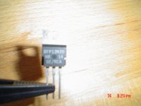
I bolted L-brackets that held 3 TO220's each on heatsinks with silpad sheet.
Worked wonderfull, less than 0.5 C difference between bracket and heatsink.
50 watt in class A from 6 TO220 devices, the heatsinks never reached 50 C.
Below is a picture of a spare TO220.
Did not have the stamina to use the bracket instead of the drains though.
Attachments
- Home
- Amplifiers
- Solid State
- Krell KSA 50 PCB