Yes bigger. Thanks.
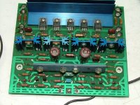
It does appear that there are three solder points in the opposite side of the board from the blue heat sinks.
The two solder points on the outside are BOTH tied to the ground grid. The center I ASSUME is the signal input. One of the side points are the signal ground, and the other I would ASSUME was a chassis or PSU tie point.
Am I correct in ASSUMING this?
Also, I see 13(!) heat sinked devices on that PCB, yet on ours I think there was a need for 1 and possibly 3.
Why the drastic difference in numbers?
acenovelty said:Somehow got the idea that individual ground wires in a star config to one central location was the solution to ground faults, hummmm, etc.
Not so?
Prosit
In a perfect world, perhaps.... anyway, Nelson, slone etc advocate the same especially for grounding the input.
rabstg said:Yes bigger. Thanks.
It does appear that there are three solder points in the opposite side of the board from the blue heat sinks.
The two solder points on the outside are BOTH tied to the ground grid. The center I ASSUME is the signal input. One of the side points are the signal ground, and the other I would ASSUME was a chassis or PSU tie point.
Am I correct in ASSUMING this?
Also, I see 13(!) heat sinked devices on that PCB, yet on ours I think there was a need for 1 and possibly 3.
Why the drastic difference in numbers?
The KSA-100 actually has another 4 extra TO-220 jap transistors (toshiba i believe vpn*** whatever)... Not sure why... maybe that makes the difference with the sound?
No idea..... even on the last pic just posted of a KSA-50 it appears to have more to-220's on the board (heatsunk also)...
Wierd
acenovelty said:rabstg,
Seems our clone board departs from pics of the original in a somewhat drastic fashion.
Yes it does PHYSICALLY, but electrically it "might" be identical.
My only point was that if the RCA input connector is isolated from the chassis via insulated washers then the main board HAS to have some connection as to reference ground.
The picture I asked to be reposted (in MY opinion) confirms that we need to tie the input ground to the chassis/PSU ground by some means..
I will likely start with a straight wire but if there is noise then trouble shoot by using a 10 Ohm resistor in series.
Please bare in mind I have not started construction yet(have not broken down and allocated time to research/order the parts), but I have been monitoring the thread for tips from others who have started.
acenovelty said:Here's my copy of a schematic. Authentic, accurate???
Prosit
What is the source of the PDF?
Was it a document put out by Krell? If not then it's authenticity cannot be verified.
I will review it for accuracy though...
")
acenovelty said:Here's my copy of a schematic. Authentic, accurate???
Prosit
I've got that one and another... They are similar, i haven't carefully studied them for differences, but our layout is definately different, but circuit paths are similar and i think our boards are right TBH...
Aaron
acenovelty - that schematic is partially wrong, the actual circuit may be right, but some of the component values look wrong... like the 470uf caps close to the input side, i was sure these were 1000uf in the original....
Hey - someone here mentioned earlier they had a KSA-50 didn't they? Does anyone know someone??? Why don't we just crack the top off and take some photo's???
Wouldn't that solve every question we have?
Hey - someone here mentioned earlier they had a KSA-50 didn't they? Does anyone know someone??? Why don't we just crack the top off and take some photo's???
Wouldn't that solve every question we have?
improvements
Hi All,
The pair of 1000u caps back to back make a slightly higher quality version of the original 470u cap in the pre1983 schematic. I think these were 'normal' post 83. As a benefit, in the event that the wrong polarity DC offset is slowly built up the 470 cap could end up reverse biased and fail. The pair of 1000u caps is a better solution sonically and from a reliability perspective. If my math is correct, with 500u the gain of the amp drops to unity at about 0.2hz, personally I'm compromising and using a pair of 390u back to back (195u total), relegating it to 'only' a 0.5hz unity gain point.
The board has to have a single wire to the best ground you can make, and this should be the return point for the loudspeaker as well. This common point of return is the centre of the star. The star configuration keeps all points in the circuit that reference ground seeing the same voltage. If you daisy chain ground points, stray voltages from high ground currents can modulate the signal grounds introducing nasties. Hence, in this case, we don't route any high current grounds through the board.
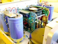
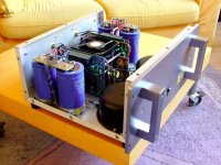
One scheme seen in many amps is to use a sheet of some metal, probably copper or aluminium, as the ground. The power supply caps 'bolt' to it, and it serves as a heatsink for the rectifiers. You can see the KSA50 does this.
Hope that helps
Stuart
Hi All,
The pair of 1000u caps back to back make a slightly higher quality version of the original 470u cap in the pre1983 schematic. I think these were 'normal' post 83. As a benefit, in the event that the wrong polarity DC offset is slowly built up the 470 cap could end up reverse biased and fail. The pair of 1000u caps is a better solution sonically and from a reliability perspective. If my math is correct, with 500u the gain of the amp drops to unity at about 0.2hz, personally I'm compromising and using a pair of 390u back to back (195u total), relegating it to 'only' a 0.5hz unity gain point.
The board has to have a single wire to the best ground you can make, and this should be the return point for the loudspeaker as well. This common point of return is the centre of the star. The star configuration keeps all points in the circuit that reference ground seeing the same voltage. If you daisy chain ground points, stray voltages from high ground currents can modulate the signal grounds introducing nasties. Hence, in this case, we don't route any high current grounds through the board.
One scheme seen in many amps is to use a sheet of some metal, probably copper or aluminium, as the ground. The power supply caps 'bolt' to it, and it serves as a heatsink for the rectifiers. You can see the KSA50 does this.
Hope that helps
Stuart
rabstg,
On the KSA-100 MK-2 they used a pair of drivers for every two pairs of output devices. So there are really two sets of driver transistor and one bias transistor on that blue heat sink! Check out this schematic of just the driver board from the same site as the board photo.....
http://home.ca.inter.net/~lloyd.maclean/Krell/MAINBD.pdf
I hope this clarifys things a bit. I'm machining my sinks to be very similar to the originals although mine will sit vertically on the board with the bias teansistor wired to the board and located midway on the sink between the two driver transistors.
Mark
Hi all, i found in post 14 by Zcolic2 and ACD in post 16 this link to the MK3 version.
http://digilander.libero.it/hienddgl/files/Ampli Krell.zip
In the scematic you can see 3 symbols for the ground connections...
I think this can be helpfull in the grounding questions.
Loek
http://digilander.libero.it/hienddgl/files/Ampli Krell.zip
In the scematic you can see 3 symbols for the ground connections...
I think this can be helpfull in the grounding questions.
Loek
- Home
- Amplifiers
- Solid State
- Krell KSA 50 PCB