 .
.I have used hundreds of the things...
...and never had one be shorted straight from the bag, you one lucky SOB, pity it wasnt good luck...
If you find many more that are 'bad' let me know, I'll send out more, perhaps the new box I opened had some bad ones...
Stuart
PS unless you have a pretty good meter it's pretty hard to accurately measure resistance that low...
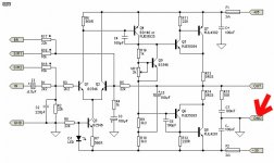
I intent to connect the LS ground direct to the PSU, like any other "power grounds". On the mainboard i see a connection pad for signal input, and a connection pad for signal ground.
I dont see any connection pad on the main board to connect all signal grounds from the main board to anything else. Do i miss something??
I dont see any connection pad on the main board to connect all signal grounds from the main board to anything else. Do i miss something??
Acenovelty, I think my question is not as stupide as you suggest. The boards of all power amps i build have a connection pad to connect the signal ground (maybey with a resistor of 10 Ohm or something) to the power ground of the PSU.
Lets turn around the case: Acenovelty, from witch point of the main board do you connect the signal ground to the power ground (PSU or wathever)?
Lets turn around the case: Acenovelty, from witch point of the main board do you connect the signal ground to the power ground (PSU or wathever)?
Ummmm wim,
I have not suggested your question is stupid.
There are a number of features on this board not required for a clone of this classic amp. Seems there are also features normally required that are not included.
I can not find a star ground point(often called "control" ground) for the PSU on the board either. Hence my comment not directed to you at all..
Curious?
Even Rod's P3A has this feature.
Attachments
ground
The amp has a high enough current potential that you definitely do not want to route the LS ground through traces on the main board. The only points on the main board that need ground have a pretty good track thickness, and this should have a stout cable to the HQ ground, which should be a spur from the cross bar between the main caps, which is also where the LS return will want to go.
Stuart
grounded
Doh, you are quite right, there doesn't seem to be a hole in the board for attaching a second heavy ground wire to the HQ ground. I was planning to solder directly onto the track underneath and hadn't bothered looking until now...guess people are gonna have to drill a hole...
Stuart
Doh, you are quite right, there doesn't seem to be a hole in the board for attaching a second heavy ground wire to the HQ ground. I was planning to solder directly onto the track underneath and hadn't bothered looking until now...guess people are gonna have to drill a hole...
Stuart
Hi-
I think Wim is looking for the tie point of the main board to the PSU ground.
I have looked at the main board again myself and other than the input ground, there are NO spots to tie the main board to a ground reference.
I would ASSUME that where the input ground connection point is I could add a 10 Ohm resistor(parallel) and tie the main board to the PSU ground or tie it to the chassis through the PCB mounting screws.
But I would expect the main board would require some type of reference to the chassis/PSU ground for the input signal.
Please advise oh wise ones,
Troy

Star ground?
As i remember the reason this was not added is that it does not exist on the original schematics... nor does it on the KSA-100 schematics either...
Unless i've missed something? Is it really necessary? Was there a reason krell left it off? (or every schematic is wrong?)
Aaron
As i remember the reason this was not added is that it does not exist on the original schematics... nor does it on the KSA-100 schematics either...
Unless i've missed something? Is it really necessary? Was there a reason krell left it off? (or every schematic is wrong?)
Aaron
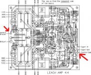
Mark A. Gulbrandsen said:[BIn the photo the blue heatsink at the top has the drivers on it and the bias transistor.
Mark [/B]
Hi Mark and all-
Any chance that someone has a bigger picture of this board and not mind posting?
Edit: Picture didn't follow... Marks post # 849
http://www.diyaudio.com/forums/showthread.php?postid=579223#post579223
in this amp...
... the 'star' ground, is off the board. You need to run the ground return from the LS to the HQ (star) ground, which as I mentioned should be a spur off the main 'bar' between the caps. The board ground, which is also the signal ground, needs to go there as well, with a 10ohm resistor in series if you like.The ground track on the board is huge relative to the currents expected to be moving in it, so there should be virtually no modulation of the voltages from one end to the other.
From a purely theoretical perspective, and if you were a perfectionist, you'd want to do the same with the positive and negative feeds too...
Stuart
Just a thought, some connections to the star gnd may result in induced hum.
To eradicate this , especially in the input coupling to gnd, a resister can be used to limit the high currents flowing in the gnd. Any value of 10 ohms to 150 ohms can be employed (depending on the connection) to reduce this hum if it happens.
Ofcourse, you need to know for which points should you have a near zero impedance connection to Gnd and which ones are ok via a resistor...")
PS: Stuart, your trannies are on route.
To eradicate this , especially in the input coupling to gnd, a resister can be used to limit the high currents flowing in the gnd. Any value of 10 ohms to 150 ohms can be employed (depending on the connection) to reduce this hum if it happens.
Ofcourse, you need to know for which points should you have a near zero impedance connection to Gnd and which ones are ok via a resistor...
PS: Stuart, your trannies are on route.
- Home
- Amplifiers
- Solid State
- Krell KSA 50 PCB